Auxiliary mechanical arm used for live working and robot

A technology for auxiliary machinery and live work, applied in the direction of manipulators, claw arms, manufacturing tools, etc., can solve the problems of inability to complete grasping, inability to accurately control positions, simple structure, etc., and achieve light weight, high positioning accuracy, grasping and The effect of large lifting weight

Inactive Publication Date: 2017-01-11
STATE GRID INTELLIGENCE TECH CO LTD
View PDF6 Cites 10 Cited by
  • Summary
  • Abstract
  • Description
  • Claims
  • Application Information

AI Technical Summary

Problems solved by technology

The existing auxiliary mechanical arm has a simple structure and does not have a position sensor, so it cannot perform precise position control, and the existing auxiliary mechanical arm has no claws at the end and cannot complete complex tasks such as grasping

Method used


Image

  • Auxiliary mechanical arm used for live working and robot
  • Auxiliary mechanical arm used for live working and robot
  • Auxiliary mechanical arm used for live working and robot

Examples


Embodiment Construction

[0031] The present invention will be described in detail below in conjunction with the accompanying drawings.

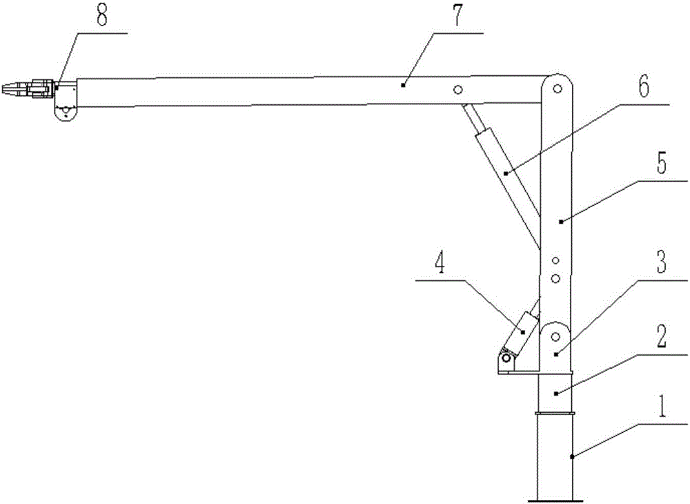
[0032] Such as figure 1 As shown, an auxiliary mechanical arm for live work includes 1 base, 2 swing cylinders, 3 large arm bases, 4 large arm cylinders, 5 large arms, 6 forearm cylinders, 7 forearms, and 8 claws.

[0033] The swing cylinder 2 is connected to the base 1 through screws, the boom base 3 is connected to the swing cylinder 2 through one end of the screw, and the other end is connected to the boom 5, and the boom cylinder 4 is connected to the boom base 3 through one end of the screw , the other end is connected to the upper arm 5, the forearm 7 is connected with the upper arm 5 by screws, the forearm oil cylinder 6 is connected to the upper arm 5 by screws at one end, and the other end is connected to the forearm 7, and the claw 8 is connected by screws, Attached to the forearm 7. The driving conditions of each degree of freedom are as follows. The rot...


PUM


Abstract

The invention discloses an auxiliary mechanical arm used for live working and a robot. The auxiliary mechanical arm comprises a base, a large arm, a front arm and a gripper. A hydraulic swing oil cylinder is arranged on the base and drives the large arm to rotate by 180 degrees in the horizontal plane. A pitching oil cylinder I driving the large arm to do pitching motion is hinged to the large arm. The front arm perpendicular to the tail end of the large arm is hinged to the tail end of the large arm. The front arm is driven by a pitching oil cylinder II to do pitching motion. The gripper is installed at the tail end of the front arm. The front arm is made of insulating material glass fiber reinforced plastic and can conduct direct live working. The auxiliary mechanical arm comprises the gripper which can be freely opened and closed and can freely conduct grasping.

Description

technical field [0001] The invention relates to the field of live work in distribution network, specifically, an auxiliary mechanical arm related to a high-voltage live work robot, which is mainly used in conjunction with a master-slave mechanical arm to complete the replacement of crossarms and transformers in live work in power distribution. Wait for heavy duty tasks. Background technique [0002] In order to improve the automation level and safety of live work, reduce the labor intensity of operators and the personal threat of strong electromagnetic fields to operators, the application of live work robots in live work in distribution networks will become more and more extensive, and the work items will be more comprehensive. , In full compliance with the requirements of power distribution live work. [0003] After years of research and practice, the live working robot has completed the research and development of the laboratory prototype. Through a large number of field ...

Claims


Application Information

Patent Timeline
Patent Type & Authority Applications(China)
IPC IPC(8): B25J18/00B25J3/04
CPCB25J18/00B25J3/04
Inventor 赵玉良戚晖刘继志阮鹏程王海磊任志刚苏建军慕世友李超英傅孟潮李建祥赵金龙
Owner STATE GRID INTELLIGENCE TECH CO LTD
Why Eureka
Try Eureka