Four-door elevator

A four-door and elevator technology, which is applied to elevators, lifts, transportation and packaging in buildings to achieve the effects of high structural strength, stable operation and strong bearing capacity

Active Publication Date: 2017-01-11
LGEER ELEVATOR
View PDF5 Cites 7 Cited by
  • Summary
  • Abstract
  • Description
  • Claims
  • Application Information

AI Technical Summary

Problems solved by technology

Traditional elevators are generally divided into single-door or front-to-back door elevators. For buildings with small shafts or special requirements, doors need to be opened in four directions to achieve the purpose of quickly entering and exiting the elevator. Traditional elevators will not be able to achieve this effect.

Method used


Image

  • Four-door elevator
  • Four-door elevator
  • Four-door elevator

Examples


Embodiment 1

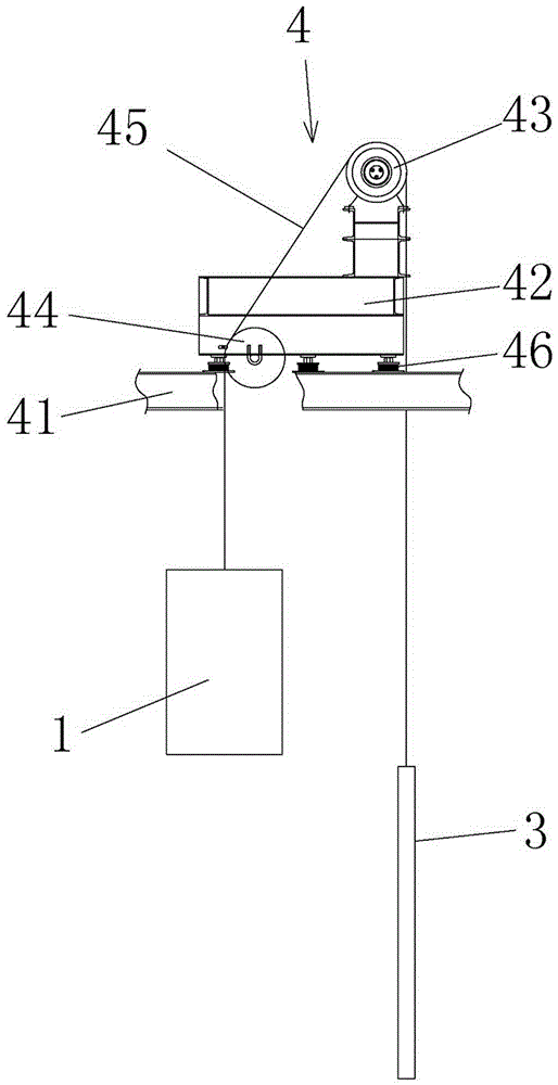
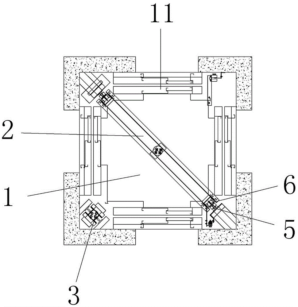
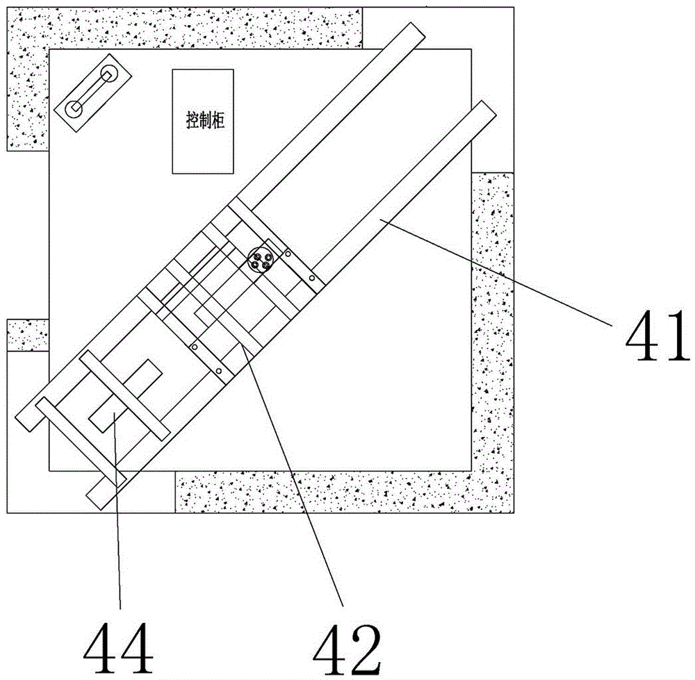
[0029] Embodiment 1: as Figure 1 to Figure 7 As shown, a four-door elevator includes a car, a car frame 2, a car guide rail 5, a counterweight device 3 and a traction device 4. The hoistway is a rectangular structure, and landing doors are arranged around the hoistway. Car doors 11 opposite to the landing doors and door operators that drive the opening and closing of the car doors 11 are respectively provided in the four directions of the horizontal direction, front, rear, left, and right. The car doors 11 adopt conventional side-opening double doors, and the door operators are conventional door operators. . The car wall and the car door are provided with sound insulation cotton, and the well wall of the shaft is provided with a magnetic isolation plate.

[0030] Such as figure 2 and Figure 4 As shown, the car frame 2 includes an upper beam 21, a lower beam 23 and a column 22, and the lower beam 23 is arranged below the car and on the diagonal line of the bottom surface ...

Embodiment 2

[0034] Embodiment 2: as Figure 8 and Figure 9As shown, the difference from Embodiment 1 is that semicircular brackets 24 are provided on both sides of the lower beam 23, and the two brackets 24 form a circle for supporting the car chassis 25. shape support structure. The bracket 24 includes an inner supporting plate 241, an outer supporting plate 243 and a top plate 242, the inner supporting plate 241, the outer supporting plate 243 and the top plate 242 form a C-shaped structure with the opening facing downward, the inner supporting plate 241 and the The outer support plates 243 are provided with round holes 244, and the upper end surface of the top plate 242 is an arc-shaped surface.

[0035] Such as Figure 10 As shown, the end of the bracket 24 is provided with a fixed end 245 for fixing on the lower beam 23, and the two sides of the fixed end 245 are provided with installation parts 2451, and the installation parts 2451 are fixed on the On the lower beam 23, the upp...


PUM


Abstract

The invention relates to the technical field of elevators, in particular to a four-door elevator which comprises an elevator car, an elevator car frame, elevator car guide rails, a counterweight device and a traction device. The elevator car is provided with car doors in the front direction, the rear direction, the left direction and the right direction of the horizontal direction and portal cranes for driving the car doors to be opened or closed. The elevator car frame comprises an upper beam, a lower beam and columns, the lower beam is arranged below the elevator car and located on the diagonal of the bottom surface of the elevator car, and the columns are vertically arranged on the two opposite angle sides of the elevator car. The elevator car guide rails are vertically arranged and disposed on the same side of the columns. The counterweight device comprises a counterweight frame, a counterweight block and a counterweight guide rail. The counterweight frame is arranged on one side of the elevator car and is in triangular distribution with the elevator car guide rails. According to the four-door elevator, the opening and closing of each car door can be controlled independently, people in different directions can enter the elevator conveniently, people go in and out of the elevator quickly, the conveying efficiency of the elevator is improved, and the counterweight frame is high in structural strength and bearing capacity and operates stably.

Description

technical field [0001] The invention relates to the technical field of elevators, in particular to a four-door elevator. Background technique [0002] In daily life, elevators come in various forms and are used in many occasions, bringing convenience to people's life and work. Elevators are vertical elevators, equipped with box-type gondolas, called cars, for carrying and transporting people or materials. The car is generally composed of main components such as the car floor, car wall, car roof, and car door. The door seen when the elevator is closed in the elevator is the car door. Traditional elevators are generally divided into single-door or front-to-back door elevators. For buildings with small shafts or special requirements, doors need to be opened in four directions to achieve the purpose of quickly entering and exiting the elevator. Traditional elevators will not be able to achieve this effect. Contents of the invention [0003] An object of the present invention...

Claims


Application Information

Patent Timeline
Patent Type & Authority Applications(China)
IPC IPC(8): B66B11/02B66B11/08B66B13/12B66B7/02B66B7/04
CPCB66B7/02B66B7/042B66B11/0206B66B11/0226B66B11/08B66B13/12
Inventor 施健杰倪群邱健健
Owner LGEER ELEVATOR
Why Eureka
Try Eureka