
lawn parking space

A technology for parking spaces and lawns, which is applied to the field of lawn parking spaces, can solve the problems of imperfect manpower driving device operation functionality, poor vibration stability adaptability, and insufficient operational reliability, and achieves avoiding mechanical damage, operating safety, Easy to maintain and feasible effect

Active Publication Date: 2019-01-18
朱力山
View PDF6 Cites 0 Cited by
  • Summary
  • Abstract
  • Description
  • Claims
  • Application Information

AI Technical Summary

Problems solved by technology

However, there are two rows of guide wheels on the vehicle-carrying board of this parking space, and the space height allowed by the actual vehicle-carrying board is limited, causing the size of the guide wheel parts to be small. The guide position and thickness of the wheel and guide rail are limited, so the overall rigidity is low, the structure is more complicated, and the operation reliability is not good enough; the operation function of the human drive device used is not very perfect; The shock stability and related installation on the road are also poor

Method used


Image

  • lawn parking space
  • lawn parking space
  • lawn parking space

Examples


Embodiment 1

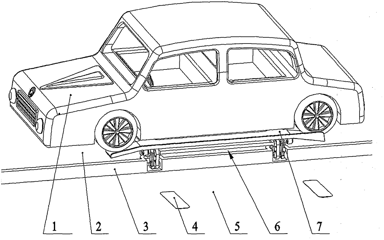
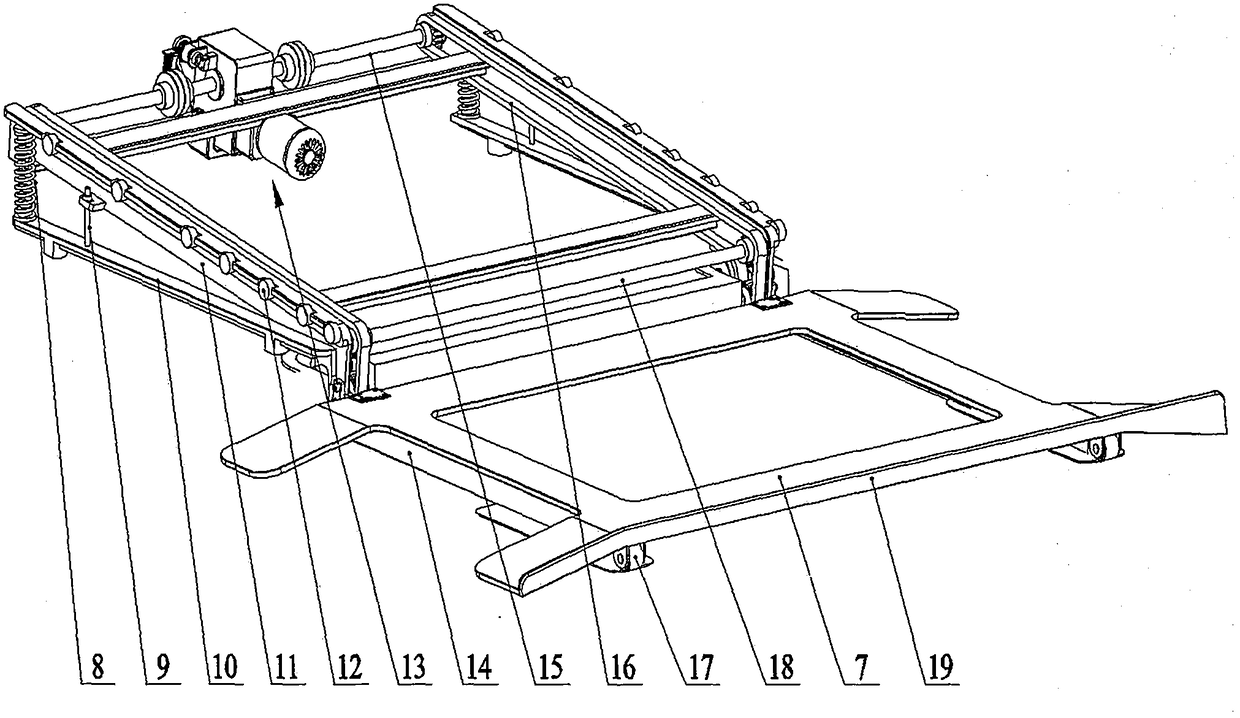
[0028] Such as Figure 1 to Figure 5 shown. A lawn parking space 6, comprising a base 10, a frame 11, a vehicle carrying plate 7 and the like.

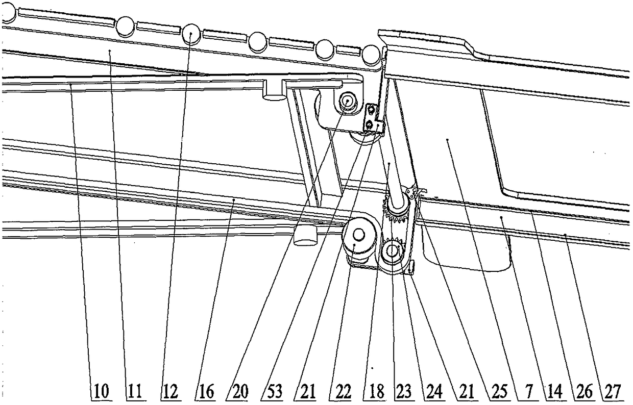
[0029] Described pedestal 10 is fixed on the foundation below lawn 2, bearing 20 is equipped with in the front portion of pedestal 10, and spring 8 is equipped with in the rear portion of pedestal 10, and limit bolt 9 is also housed on pedestal 10.

[0030] The fixed short shafts on both sides of the front end of the frame 11 are articulated and installed in the bearing 20 of the base 10; the rear end of the frame 11 is placed on the spring 8 of the base 10; Determine the maximum deployment angle required by the frame 11 and the base 10 during operation.

[0031] The frame 11 is provided with parallel guide wheel sets 12, and two guide grooves 14 are installed on both sides of the bottom surface of the vehicle-carrying plate 7, and the upper guide rail 26 and the lower guide rail 27 in the guide groove 14 can make the vehicle The p...

Embodiment 2

[0042] like Image 6 As shown, in order to make the visual area of ​​the parking space 6 on the lawn 2 smaller when unloaded, it is possible to design the upper and lower car guide plate structures on both sides of the vehicle-carrying plate 7 to be formed by a turning plate 50, a hinge 49 and a supporting plate 48. Structural form, after the flap 50 is turned over, the space in the vision is larger; the support plate 48 can support the weight of the trolley 1 and adjust the deployment angle, and the deployment angle of the flap 50 when storing the car is the same as that without the hinge 49 and the support plate The angle of the vehicle-loading plate 7 of 48 is the same, and can be opened or closed when unloaded. The deflection correcting turnover panel 51 fixed on the turnover panel 50 and the side panel 52 on the vehicle-carrying plate 7 can calibrate and warn the collimation alignment when getting on the bus.

[0043] The conventional electronic control operation process...


PUM


Abstract

The invention relates to a lawn parking space allowing a car to park on the roadside lawn and solves the problem of difficulty in parking of the car in society. A frame hinged to the lawn base is designed, guide wheel groups are mounted on two sides of the frame, driving chains, driving chain wheels, an upper driven chain wheel and a lower driven chain wheel are mounted on the frame, the driving chains are in tractive connection with a car loading board, and upper guide rails and lower guide rails mounted on the car loading board can move on the frame; power-driven, hand-cranking and foot-stepping driving mechanisms are mounted at the rear end of the frame; a limit stabilizer is mounted in the loading and unloading position of the car loading board on the road; loading and unloading guide plates on two sides of the car loading board can be in a form of turning plates. The lawn parking space has the beneficial effects as follows: parking on the roadside lawn at night is realized, furthermore, the lawn ecology is not influenced, turning backing-up is not needed during car parking and taking, one-key control is realized, the lawn parking space can be used through hand cranking or foot stepping when losing power, the structural operation is stable, the occupied area is small, and the lawn parking space is equipment capable of solving the problem of difficulty in parking of the car.

Description

technical field [0001] The invention relates to a lawn parking space for parking small cars on the roadside, especially on the roadside lawn. Background technique [0002] With the development of society, the increase of cars is very fast, causing the shortage of parking spaces in the society. For this reason, many forms of parking garages have occurred. However, it is very difficult to build a new parking garage for the built-up building environment or the difficult parking situation in the existing community. Therefore it is common to park on the roadside, and even dollies are parked on the roadside greening lawn, which destroys the greening environment and management, and some parking space devices built on the lawn have appeared for this reason. But the seen lawn parking device is basically installed on the lawn by the vertical road, the parking operation is not very convenient, the required greening depth space for parking is larger, and the appearance and the environm...

Claims


Application Information

Patent Timeline
Patent Type & Authority Patents(China)
IPC IPC(8): E04H6/06
CPCE04H6/065
Inventor 朱力山
Owner 朱力山
Learn More