
Downhole breaking rock-entering drill of hydraulic slewing drilling machine

A rotary drilling rig and down-the-hole technology, which is applied to drilling equipment, earthwork drilling, and driving devices for drilling in boreholes. Fast response, good anti-rotation effect, fast hole forming effect

Inactive Publication Date: 2017-01-11
XIANGYANG CHANGKAN INTELLIGENT MACHINERY
View PDF6 Cites 2 Cited by
  • Summary
  • Abstract
  • Description
  • Claims
  • Application Information

AI Technical Summary

Problems solved by technology

[0002] The power head type full hydraulic rotary drilling rig currently used, once it encounters a rock formation during the drilling process, it is difficult for the original drill bit to enter the rock quickly, and the drilling efficiency is extremely low. The traditional drilling method relies on the grinding of the drill teeth at the bottom of the drill bit. When encountering a rock formation with a hardness of 100 MPa and above, its rock-penetrating speed is only about 1 meter in 10 hours.
Although the use of a pneumatic down-the-hole hammer can impact the rock formation, the efficiency is low. The larger the diameter of the pile hole, the higher the cost of the down-the-hole hammer, and it is impossible to realize the one-time impact of a large-diameter pile hole into a hole. Multiple reaming is required. Realize continuous slag discharge at the bottom of the hole, and the rock entry speed is relatively slow

Method used


Image

  • Downhole breaking rock-entering drill of hydraulic slewing drilling machine
  • Downhole breaking rock-entering drill of hydraulic slewing drilling machine

Examples


Embodiment Construction

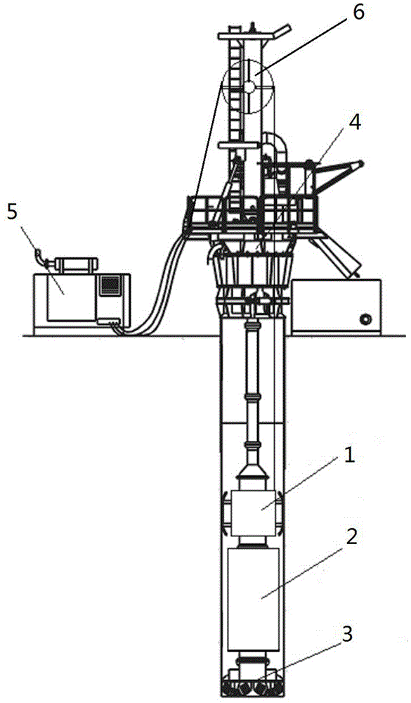
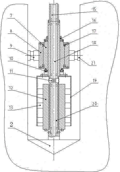
[0013] like figure 1 , 2 As shown, the drill pipe 15 of the rotary drilling rig 4 of the rotary drilling rig of the present invention is equipped with an oil circuit rotary joint assembly 1, and the lower end of the rotary joint assembly 1 is connected with the drill bit 3 through the vibrator 2; Assembly 1 is composed of moving ring 7, static ring 8 and anti-rotation mechanism 9. The rotating joint assembly 1 moving ring 7 is a cylinder with a central through hole, and the moving ring 7 is sleeved on the central shaft 18 through the central through hole; the center The shaft 18 is a transitional drill pipe, the upper end of the central shaft 18 is connected to the drill pipe 15 of the rotary drilling rig through a flange, and the central through hole on the central shaft 18 is connected with the drill slag gas lift channel on the drill pipe 15; the static ring 8 is A cylinder with a central through hole, the static ring 8 is fitted on the outer circumference of the moving ri...


PUM


Abstract

The invention provides a downhole breaking rock-entering drill of a hydraulic slewing drilling machine and relates to a rock breaking device applicable to a power head type full hydraulic slewing drilling machine. The problems that in the drilling process, once an existing power head type full hydraulic slewing drilling machine encounters a rock stratum, a drill bit cannot enter the rock easily, the drilling efficiency is low, one-time impact holing of a large-diameter pile hole cannot be achieved, continuous hole bottom slag discharge cannot be achieved, the rock entering speed is slow, the drill bit is severely abraded, and the cost is high are solved. An oil circuit rotating connector assembly is additionally arranged on a drill rod of the slewing drilling machine. A central shaft of the rotating connector assembly is connected with the drill rod through a flange. The lower end of the rotating connector assembly is connected with a gas lifting hard rock drill bit through a vibrator. In the drilling and rock entering processes, percussive drilling is adopted, the rock entering and drilling efficiency is improved, continuous gas lifting slag discharge of the drilling machine is not changed while the vibrator conducts vibrating striking to cooperate with drilling of a drill bit, and the functions of striking and drilling of the power head type full hydraulic slewing drilling machine are achieved.

Description

technical field [0001] The invention relates to a power head type full hydraulic rotary drilling rig, in particular to a down-the-hole crushing rock drill suitable for the power head type full hydraulic rotary drilling rig for rock drilling. Background technique [0002] The power head type full hydraulic rotary drilling rig currently used, once it encounters a rock formation during the drilling process, it is difficult for the original drill bit to enter the rock quickly, and the drilling efficiency is extremely low. The traditional drilling method relies on the grinding of the drill teeth at the bottom of the drill bit. When encountering a rock formation with a hardness of 100 MPa and above, its rock-penetrating speed is only about 1 meter in 10 hours. Although the use of a pneumatic down-the-hole hammer can impact the rock formation, the efficiency is low. The larger the diameter of the pile hole, the higher the cost of the down-the-hole hammer, and it is impossible to re...

Claims


Application Information

Patent Timeline
IPC IPC(8): E21B4/06E21B4/14
Inventor 邵波
Owner XIANGYANG CHANGKAN INTELLIGENT MACHINERY
Learn More