Shaft assembly
A technology of shaft assembly and assembly, applied in the direction of bearing elements, shafts, crankshafts, etc., can solve the problems of time-consuming, expensive surface, etc.
- Summary
- Abstract
- Description
- Claims
- Application Information
AI Technical Summary
Problems solved by technology
Method used
Image
Examples
Embodiment Construction
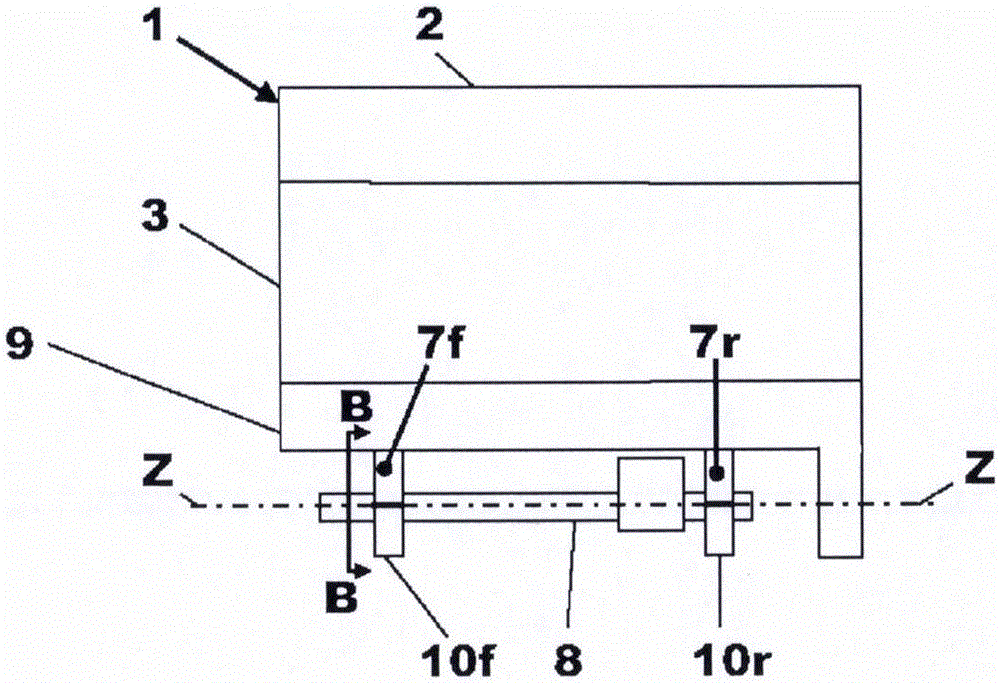
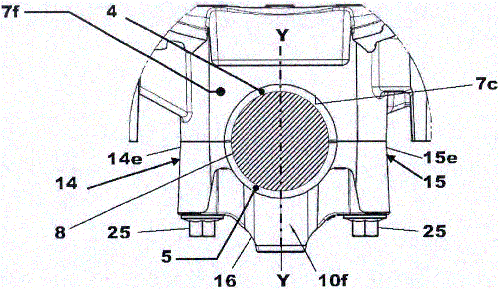
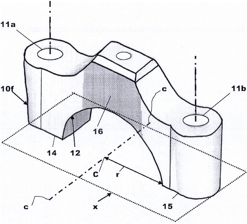
[0046] specific reference Figure 1a , Figure 1b , figure 2 and image 3 , shows an engine 1 having a cylinder head 2 , a cylinder block 3 and a trapezoidal frame 9 bolted to the lower end of the cylinder block 3 . The trapezoidal frame 9 defines at the lower end a front bearing support structure 7f and a rear bearing support structure 7r, to each of which a respective error proof bearing cap 10f, 10r is bolted by a pair of bolts 25 . The front bearing cap 10f is bolted to the front bearing support structure 7f and the rear bearing cap 10r is bolted to the rear bearing support structure 7r.
[0047] In the exemplary case where the shaft 8 is an engine balancer shaft, the shaft 8 is rotatably supported by the front bearing cap 10f and the rear bearing cap 10r and the front bearing support structure 7f and the rear bearing support structure 7r to form a shaft and bearing assembly. In the example case, the shaft 8 is rotatably supported by two bearing support assemblies 7f, ...
PUM
 Abstract
Description
Claims
Application Information
 - R&D
- Intellectual Property
- Life Sciences
- Materials
- Tech Scout
- Unparalleled Data Quality
- Higher Quality Content
- 60% Fewer Hallucinations
Browse by: Latest US Patents, China's latest patents, Technical Efficacy Thesaurus, Application Domain, Technology Topic, Popular Technical Reports.
© 2025 PatSnap. All rights reserved.Legal|Privacy policy|Modern Slavery Act Transparency Statement|Sitemap|About US| Contact US: help@patsnap.com


