Electric driving pump

An electric drive, pump shaft technology, applied in the direction of pumps, pump devices, pump components, etc., can solve the problems of hydraulic efficiency, vibration increase, impact on impeller installation, etc., to achieve the effect of increasing support points

Inactive Publication Date: 2017-01-11
ZHEJIANG SANHUA AUTOMOTIVE COMPONENTS CO LTD
View PDF10 Cites 3 Cited by
  • Summary
  • Abstract
  • Description
  • Claims
  • Application Information

AI Technical Summary

Problems solved by technology

[0005] The electric drive pump includes a pump shaft connecting the impeller and the rotor. The support of the pump shaft in the prior art mainly includes cantilever support and two-end support. The vibration of the pump shaft with cantilever support will increase, and the two-end support will affect the installation of the impeller. Hydraulic efficiency makes a difference

Method used


Image

  • Electric driving pump
  • Electric driving pump
  • Electric driving pump

Examples


Embodiment Construction

[0026] The present invention will be further described below in conjunction with the accompanying drawings and specific embodiments:

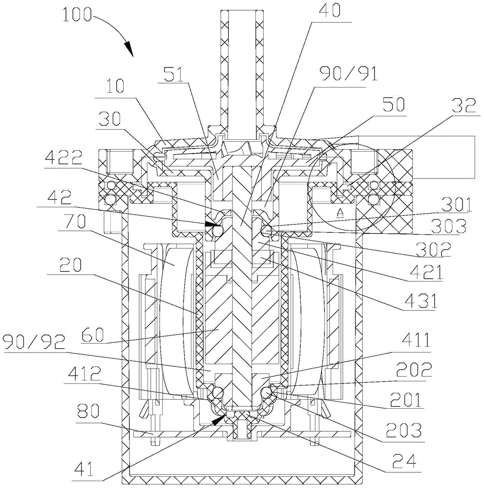
[0027] figure 1 It is a schematic structural diagram of an electric drive pump 100. The electric drive pump 100 includes an impeller cavity cover 10, an isolation sleeve 20, a pump shaft 40, an impeller 50, a rotor 60, a stator assembly 70, and an electric control board 80. The electric drive pump 100 has a flow The flow cavity 90 includes the space between the impeller cavity cover 10 and the isolation sleeve 20. The impeller 40 and the rotor 60 are arranged in the flow cavity 90. The rotor 60 can drive the impeller 50 to rotate around the central axis of the pump shaft 40. This embodiment Among them, the rotor 60 drives the impeller 50 to rotate together with the pump shaft 40, of course the pump shaft 40 can also be stationary, the rotor 60 drives the bearing sleeve and the impeller 50 sleeved on the outer peripheral surface of the pump shaf...


PUM


Abstract

The invention provides an electric driving pump. The electric driving pump comprises an impeller cavity cover, a spacer sleeve, a rotor, an impeller, a pump shaft and a circulating cavity. The pump shaft is fixedly arranged on the rotor. The impeller is supported at the other tail end of the pump shaft. The electric driving pump further comprises a first supporting part and a second supporting part which are used for supporting the pump shaft. The first supporting part comprises a first bearing and a first bearing supporting part. The first bearing supporting part is formed in the spacer sleeve. One tail end of the pump shaft is rotatably supported on the first supporting part through the first bearing. A second bearing supporting part is formed in a separation element. The middle portion of the pump shaft is supported on the second bearing supporting part through a second bearing. In this way, the pump shaft is supported more stably, and the hydraulic efficiency of the electric driving pump is not affected.

Description

[0001] 【Technical field】 [0002] The invention relates to an electric drive pump, which is specifically applied to a fluid circulation system. [0003] 【Background technique】 [0004] In recent decades, electric-driven pumps have gradually replaced traditional mechanical pumps and have been widely used in fluid circulation systems. The electric drive pump has the advantages of no electromagnetic interference, high efficiency and environmental protection, stepless speed regulation, etc., and can well meet the requirements of the market. [0005] The electric drive pump includes a pump shaft connecting the impeller and the rotor. The support of the pump shaft in the prior art mainly includes cantilever support and two-end support. The vibration of the pump shaft with cantilever support will increase, and the two-end support will affect the installation of the impeller. impact on hydraulic efficiency. [0006] Therefore, it is necessary to improve the existing technology to sol...

Claims


Application Information

Patent Timeline
Patent Type & Authority Applications(China)
IPC IPC(8): F04D13/06F04D29/42F04D29/70F04D29/046
Inventor 不公告发明人
Owner ZHEJIANG SANHUA AUTOMOTIVE COMPONENTS CO LTD
Why Eureka
Try Eureka