Compensation mechanism for stress deformation of spindle box of machine tool

A technology of stress deformation and machine tool spindle, which is applied in the direction of metal processing machinery parts, metal processing equipment, maintenance and safety accessories, etc., can solve the problems of axial deformation of the ram, stress deformation of the spindle box, etc. The effect of large span, light weight and compact structure

Inactive Publication Date: 2012-10-03
SANY GRP
View PDF1 Cites 3 Cited by
  • Summary
  • Abstract
  • Description
  • Claims
  • Application Information

AI Technical Summary

Problems solved by technology

[0005] Chinese patent CN201010248293 discloses a two-way compensation device for deflection and deformation of a ram, which mainly solves the problem that the existing rod compensation device causes the axial deformation of the ram due to the eccentricity of the rod. Rod and the thrust cylinder connected with the pressure rod, the pressure rod and the pull rod are symmetrical up and down along the centerline of the milling axis, and the left and right symmetry between the two pressure rods is symmetrical along the centerline of the milling axis, and the thrust cylinder is in the headstock
This device simply improves the internal rigidity of the ram, and cannot perform position compensation for the stress and deformation of the headstock wrapping the ram

Method used


Image

  • Compensation mechanism for stress deformation of spindle box of machine tool
  • Compensation mechanism for stress deformation of spindle box of machine tool
  • Compensation mechanism for stress deformation of spindle box of machine tool

Examples


Embodiment Construction

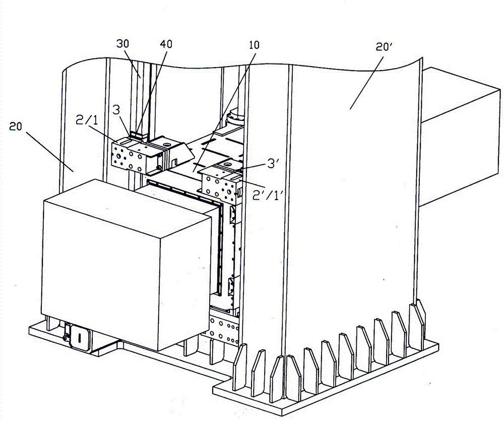
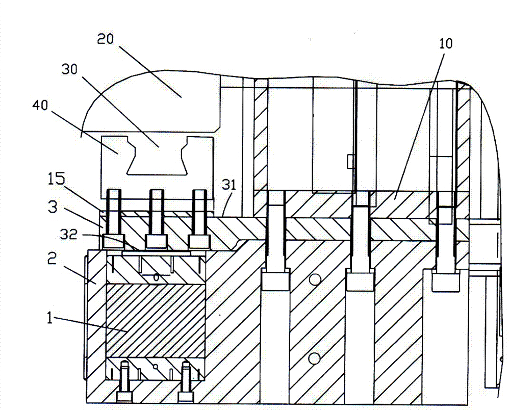
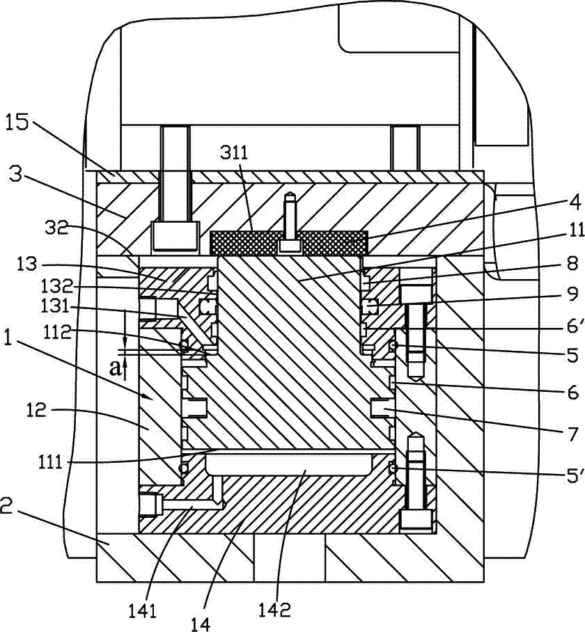
[0029] see Figure 1~Figure 3 , the compensation mechanism for the stress deformation of the spindle box of the machine tool, the spindle box 10 is located between the two columns 20, 20', forming a door-type thermal deformation symmetrical structure, and the front and rear contact surfaces between the spindle box 10 and the two columns 20, 20' are respectively Two guide rails 30 and a slider 40 are provided to form a vertical guide support.

[0030] The compensation mechanism includes two compensation oil cylinders 1, 1', which are respectively arranged in a support shell 2, 2', and the two support shells 2, 2' are symmetrically installed on both sides of the upper end surface of the rear part of the headstock 10 respectively. Two transitional connecting plates 3, 3', the two ends of one side 31 of the transitional connecting plate 3 (taking the compensation cylinder 1 and the transitional connecting plate 3 as an example, the same below) are respectively connected to one sid...


PUM


Abstract

The invention relates to a compensation mechanism for stress deformation of a spindle box of a machine tool, wherein the spindle box is arranged between two upright columns, thereby forming a gate-type thermal deformation symmetrical structure; two guide rails and sliding blocks are respectively arranged on front and back contact walls between the spindle box and the two upright columns, thereby forming a vertical guiding support; the compensation mechanism further comprises two compensation cylinders, two transition connection plates and two support shells; the two compensation cylinders arerespectively arranged in the two support shells; the two support shells are symmetrically arranged at two sides of the upper end face on the rear part of the spindle box; two ends on one side wall ofeach transition connection plate are respectively connected to two sides of the upper end face on the rear part of the spindle box and corresponding to the sliding blocks of the guide rails; the two support shells, in which the compensation cylinders are arranged, are respectively arranged on the other side walls of the transition connection plates corresponding to the sliding blocks; and the piston rod ends of the compensation cylinders prop against the other side walls of the transition connection plates corresponding to the sliding blocks. According to the compensation mechanism provided by the invention, the deformation compensation mechanism is arranged inside a sliding sleeper. The compensation mechanism provided by the invention can be used for solving the problem of suspension stretching flexible deformation caused by the change of gravity center of a spindle component in the moving process of the spindle box and can be used for dynamically compensating the stress deformation generated by the spindle box in real time.

Description

technical field [0001] The invention relates to machine tool equipment, in particular to a compensation mechanism for stress deformation of a machine tool spindle box. Background technique [0002] The spindle box is the key component of the machine tool. During the movement of the spindle box, the front end of the spindle often sags due to the change of the center of gravity, which affects the dynamic performance of the machine tool and the machining accuracy of the parts. How to design the compensation device is very important to improve the motion accuracy of the headstock. [0003] At present, many machine tool designs use front-end balance oil cylinders. One or two balance oil cylinders are arranged at the front end of the column to lift the spindle box and overcome the deformation of the spindle group due to gravity. The front balance oil cylinder often depends on the stroke of the headstock and has a large volume. If the single cylinder offset form is used, it is e...

Claims


Application Information

Patent Timeline
Patent Type & Authority Patents(China)
IPC IPC(8): B23Q11/00B23Q1/01
Inventor 周建华齐政彦孟祥东
Owner SANY GRP
Why Eureka
Try Eureka