Tool facilitating assembly of aero model

A model and aviation technology, applied in manufacturing tools, workbenches, workpiece clamping devices, etc., can solve the problems of low assembly efficiency, wrong installation of model parts, and inconvenience in the completion of aviation model production, so as to improve assembly efficiency and increase fixation. performance, avoid surface damage

Pending Publication Date: 2017-11-28
黎昀菡
View PDF4 Cites 3 Cited by
  • Summary
  • Abstract
  • Description
  • Claims
  • Application Information

AI Technical Summary

Problems solved by technology

[0006] The object of the present invention is to provide a tool that facilitates the assembly of the aircraft model, and solve the problem of holding and fixing the aircraft model body with bare hands in the manufacture of the aircraft model. The problems of incorrect parts installation and low assembly efficiency

Method used


Image

  • Tool facilitating assembly of aero model
  • Tool facilitating assembly of aero model
  • Tool facilitating assembly of aero model

Examples


Embodiment 1

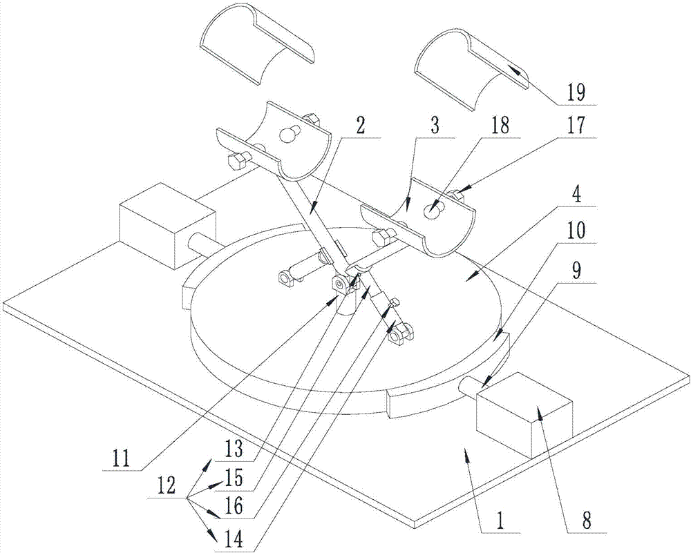
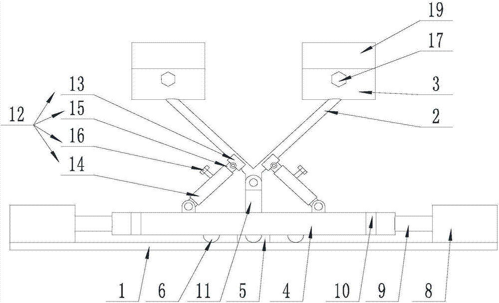
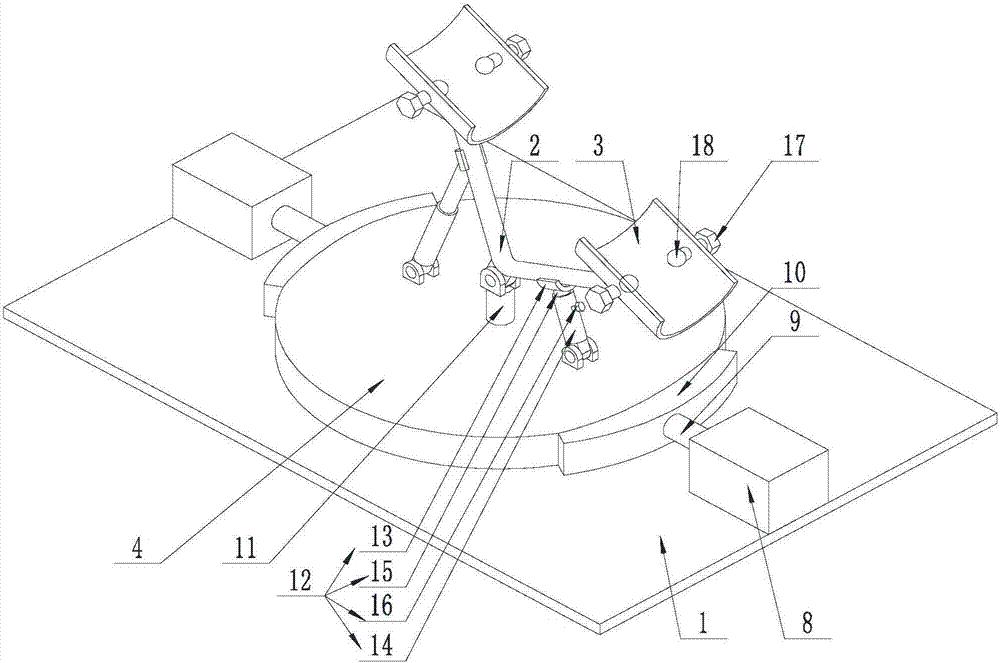
[0053] Such as Figure 1-Figure 7 As shown, the present invention facilitates the assembly of the aircraft model, including a support plate 1, on which a support rod 2 is arranged on the upper surface of the support plate 1, and the support rod 2 is bent into a V-shaped bar, and its tip is connected to the support plate. 1 connection, connecting plates 3 are arranged at their ends, and the connecting plates 3 are all arc-shaped plates, their axes coincide with each other, and their outer convex surfaces are connected with the ends of the support rods 2, and above the connecting plates 3 are provided with Pressing plate 19, on pressing plate 19, one end close to connecting plate 3 and the inner concave surface of connecting plate 3 are all provided with magnets, and the cross section of connecting plate 3 is a inferior arc shape;

[0054] Limiting bolts 17 are arranged on the side walls away from the support rod 2 on the connecting plate 3, and the limiting bolts 17 are threade...

Embodiment 2

[0060] This embodiment is based on Embodiment 1 to further illustrate the present invention.

[0061] Such as Figure 1-Figure 7 As shown, the present invention facilitates the assembly of aircraft models. Between the support plate 1 and the support rod 2, there are sequentially connected and coaxial rotating disks 4 and support shafts 5. One end of the support shaft 5 is connected to the support plate 1. Connected, the other end of the support shaft 5 is rotationally connected with the rotating disk 4; the rotating disk 4 can rotate around the axis of the supporting shaft 5, and the end of the rotating disk 4 away from the supporting shaft 5 is connected with the support rod 2, and the support rod 2 The center line coincides with the axis of the support shaft 5.

[0062] Further, three support balls 6 are arranged on the end of the rotating disk 4 close to the supporting plate 1, and the supporting balls 6 are evenly divided on the rotating disk 4 with the axis of the rotati...

Embodiment 3

[0066] This embodiment is based on the second embodiment, and further explains the position limitation of the support ball 6 .

[0067] Such as Figure 1-Figure 7 As shown, the present invention facilitates the assembly of the aircraft model. A limiting groove 7 is arranged on the upper surface of the support plate 1. The limiting groove 7 is an annular groove, and its axis coincides with the axis of the rotating disk 4, limiting The groove bottom of bit groove 7 is inferior arc shape, and its diameter is consistent with the ball diameter of support ball 6, and its center of circle is positioned in limit groove 7, and one end away from rotating disc 4 on described support ball 6 is positioned in limit groove 7, And contact with the groove bottom of limit groove 7.

[0068] Since the support ball 6 only supports the rotating disk 4, and when the rotating disk 4 is subjected to radial force, the connecting part of the supporting ball 6 and the rotating disk 4 will be subject to...


PUM


Abstract

The invention discloses a tool facilitating assembly of an aero model. The tool comprises a supporting plate. A supporting rod is arranged on the upper surface of the supporting plate. The supporting rod is bent into a V-shaped rod. The tip end of the supporting rod is connected with the supporting plate. The tail ends of the supporting rod are each provided with a connecting plate. Pressing plates are arranged over the connecting plates. The pressing plates and the connecting plates are all provided with magnets. The pressing plates are arranged over the connecting plates to make the pressing plates and the magnets on the connecting plates attract mutually so as to press the pressing plates onto parts and fix related components. Thus, in the process of manufacturing the aero model, the aero model can be supported and fixed through a working table designed by the invention so that a user can assemble the aero model conveniently, and the related components or an airplane body can be fixed; meanwhile, the conditions that installation mistakes and deviation of a preset position of model parts are caused by hand shaking and other reasons are avoided, and the assembly efficiency is improved; installation of overall components of the aero model meets the design requirements, and flying of the aero model is facilitated.

Description

technical field [0001] The invention relates to a workbench, in particular to a tool for assembling an aircraft model. Background technique [0002] Aviation model is a general term for various aircraft models, including model airplanes and other model aircraft. With the development of aviation models, especially the perfection of radio-controlled model aircraft, the use of aviation models is becoming more and more extensive. [0003] With the development of aircraft models and the holding of aircraft model competitions, in order to facilitate the design and production of users, the existing aircraft models are mainly punched out on the motherboard through the blanking process, and in order to avoid parts Damaged during transportation, the mother board and the parts are not directly punched and separated, but the runners are punched out, and then the user uses tools to cut the mother board and parts apart, and then assembles and sprays paint. [0004] The specific manufact...

Claims


Application Information

Patent Timeline
Patent Type & Authority Applications(China)
IPC IPC(8): B25B11/02B25H1/08
CPCB25B11/02B25H1/08
Inventor 黎昀菡
Owner 黎昀菡
Why Eureka
Try Eureka