Self-tapping screw

A self-tapping screw and screw body technology, applied in the direction of screws, nuts, bolts, etc., can solve the problems of potential safety hazards, impact on service life, high cost, etc., achieve significant anti-slip effects, increase service life, and prevent rust

Inactive Publication Date: 2017-01-11
TAIZHOU FENGYE METAL PROD
View PDF0 Cites 1 Cited by
  • Summary
  • Abstract
  • Description
  • Claims
  • Application Information

AI Technical Summary

Problems solved by technology

During the use of screws, it often happens that the end of the screw is exposed because the screw is too long, so that not only the screw will rust and affect the service life, but also there will be safety hazards; When the connecting parts are fastened and connected, since there is no anti-slip structure on the screw, it is necessary to use a washer to prevent the slip. However, the anti-slip method of the screw is not only complicated to assemble, but also reduces the work efficiency, and the cost is high, which increases the cost.

Method used


Image

  • Self-tapping screw
  • Self-tapping screw
  • Self-tapping screw

Examples


Embodiment 1

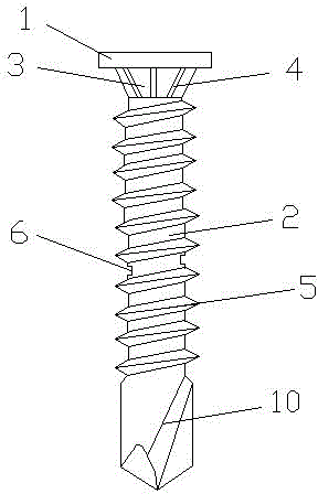
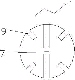
[0017] Such as figure 1 with 2 As shown, a self-tapping screw of the present invention includes a screw body, the screw body includes a nut 1 and a screw 2 at its bottom end. The screw 2 is provided with a thread 5, and the end of the screw 2 has a taper-shaped self-tapping end 3. Between the nut 1 and the screw 2 is a cone-shaped cylindrical section 3. The diameter of the small end of the cone-shaped cylindrical section 3 is the same as the diameter of the screw 2, and the diameter of the large end of the cone-shaped cylindrical section 3 is smaller than the diameter of the nut 1. The circumferential surface of the section 3 is provided with a plurality of elongated convex teeth 4, and the elongated convex teeth 4 are arranged at intervals. The two threads on the screw 2 near the self-tapping end 10 are provided with grooves 6, grooves 6 Around the screw 2 times. A cross groove 7 is formed on the upper end surface of the nut 1, and two or more rectangular opening grooves 9 are...

Embodiment 2

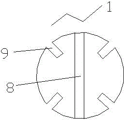
[0019] Such as figure 1 with 3 As shown, a self-tapping screw of the present invention has a groove 8 formed on the upper end surface of the nut 1, and the rest of the structure is the same as the first embodiment.

[0020] The self-tapping screw of the present invention has simple processing and simple assembly, and the plurality of elongated convex teeth 4 provided on the circumferential surface of the tapered cylindrical section 3 has a remarkable anti-slip effect. The groove 6 around the screw 2 is arranged between the two threads on the screw 2 close to the self-tapping end 10, which can easily be hit with a heavy object to break the self-tapping screw at the position where the groove is provided, thereby effectively preventing it The exposed part is rusty, which increases the service life of the screw and avoids or reduces the possible harm to the human body from the exposed part. There are also two or more rectangular opening grooves 9 formed on the upper end surface of th...


PUM


Abstract

The invention relates to a screw, in particular to a self-tapping screw. According to the technical scheme, the self-tapping screw comprises a screw body. The screw body comprises a nut and a screw rod located at the bottom end of the nut. The screw rod is provided with threads, and a self-tapping end in a pointed cone shape is arranged at the tail end of the screw rod. A tapered cylindrical section is arranged between the nut and the screw rod. The small end diameter of the tapered cylindrical section is the same as the diameter of the screw rod, and the large end diameter of the tapered cylindrical section is smaller than the diameter of the nut. A plurality of long bar-shaped convex teeth are arranged on the circumferential face of the tapered cylindrical section. All the long bar-shaped convex teeth are arranged at intervals. A groove is formed between two threads of the screw rod and located close to the self-tapping end. The self-tapping screw has the advantages that machining and assembling are simple, the antiskid effect is obvious, an exposed part can be effectively prevented from being rusted, the service life of the screw is prolonged, and possible harm to human bodies by the exposed part can be avoided or reduced.

Description

Technical field [0001] The invention relates to a screw, in particular to a self-tapping screw. Background technique [0002] Screws are fasteners used to fix objects, and they are widely used. Usually, the screws are installed in the fixed object and the screw holes of the object connected with the fixed object to perform the fixing. Screws often appear in the process of use. Because the screws are too long, the ends of the screws are exposed to the outside. This will not only rust the screws and affect the service life, but also have safety hazards. In addition, the existing screws are being When the connecting piece is fastened and connected, because the screw is not provided with an anti-skid structure, it is necessary to use a washer for anti-skid. However, the screw uses this method for anti-skid, not only the assembly is complicated, the work efficiency is reduced, but the cost is high, and the cost is increased. . Therefore, a new technical solution should be provided t...

Claims


Application Information

Patent Timeline
Patent Type & Authority Applications(China)
IPC IPC(8): F16B25/10F16B23/00F16B41/00
Inventor 赵璟
Owner TAIZHOU FENGYE METAL PROD
Why Eureka
Try Eureka