Practical gear sensor
A sensor and practical technology, applied in transmission control, components with teeth, belts/chains/gears, etc., can solve problems such as danger, difficulty in gear replacement, etc., and achieve the effect of simple structure
- Summary
- Abstract
- Description
- Claims
- Application Information
AI Technical Summary
Problems solved by technology
Method used
Image

Examples
Embodiment 1
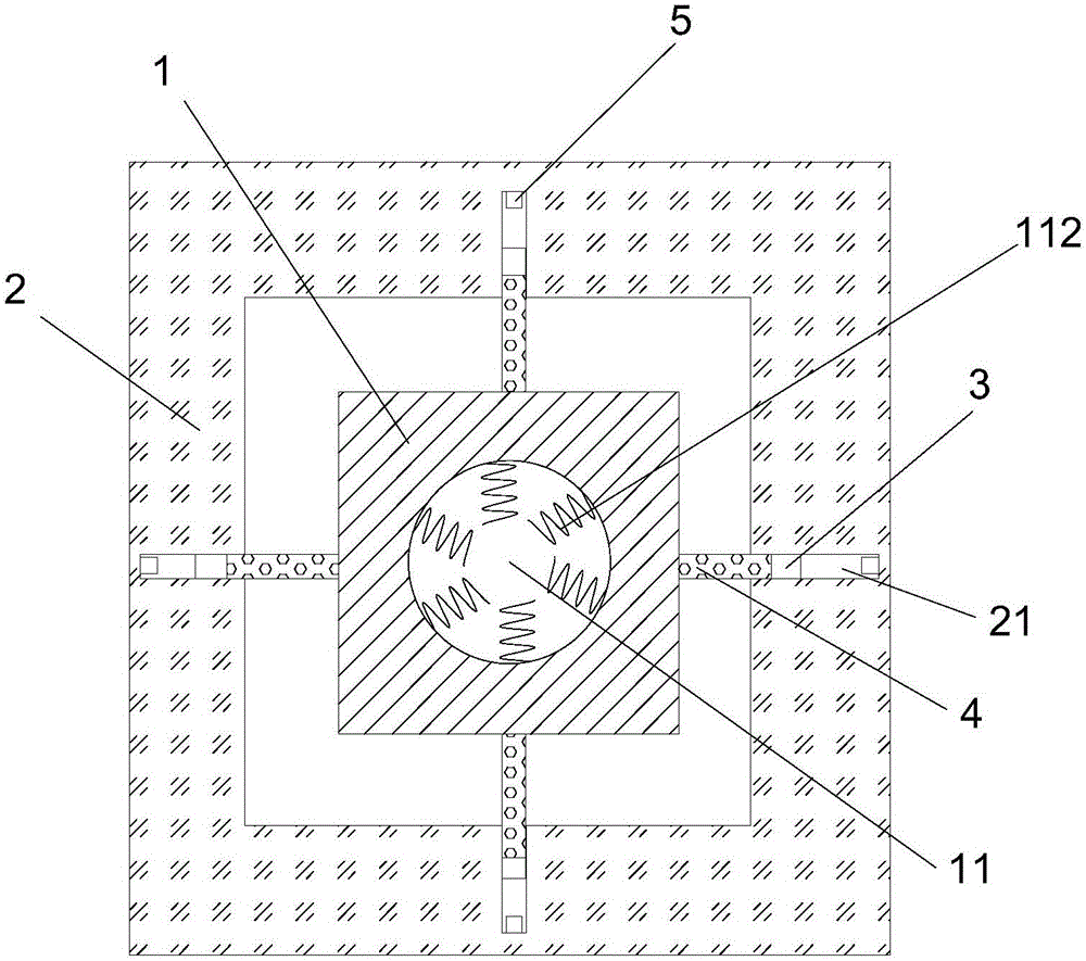
[0016] refer to figure 1 As shown, a practical gear sensor proposed by the present invention includes a moving block 1, a rectangular mounting frame 2, four magnetic parts 3, four detection auxiliary rods 4 and four magnetic sensing elements 5;
[0017] The rectangular mounting frame 2 is located on the outer periphery of the moving block 1, and the four sides of the rectangular mounting frame 2 are provided with sliding grooves 21. The openings of the sliding grooves 21 face the moving block 1, and the four magnetic parts 3 are respectively movable and installed in the four sliding grooves. In 21, the moving direction of the magnetic part 3 is the width direction of the frame edge where the four detection auxiliary rods 4 correspond to the four magnetic parts 3 one by one, and the first ends of the four detection auxiliary rods 4 are connected to the corresponding magnetic parts 3, There are four moving tracks on the moving block 1, and the four moving tracks correspond to th...
Embodiment 2
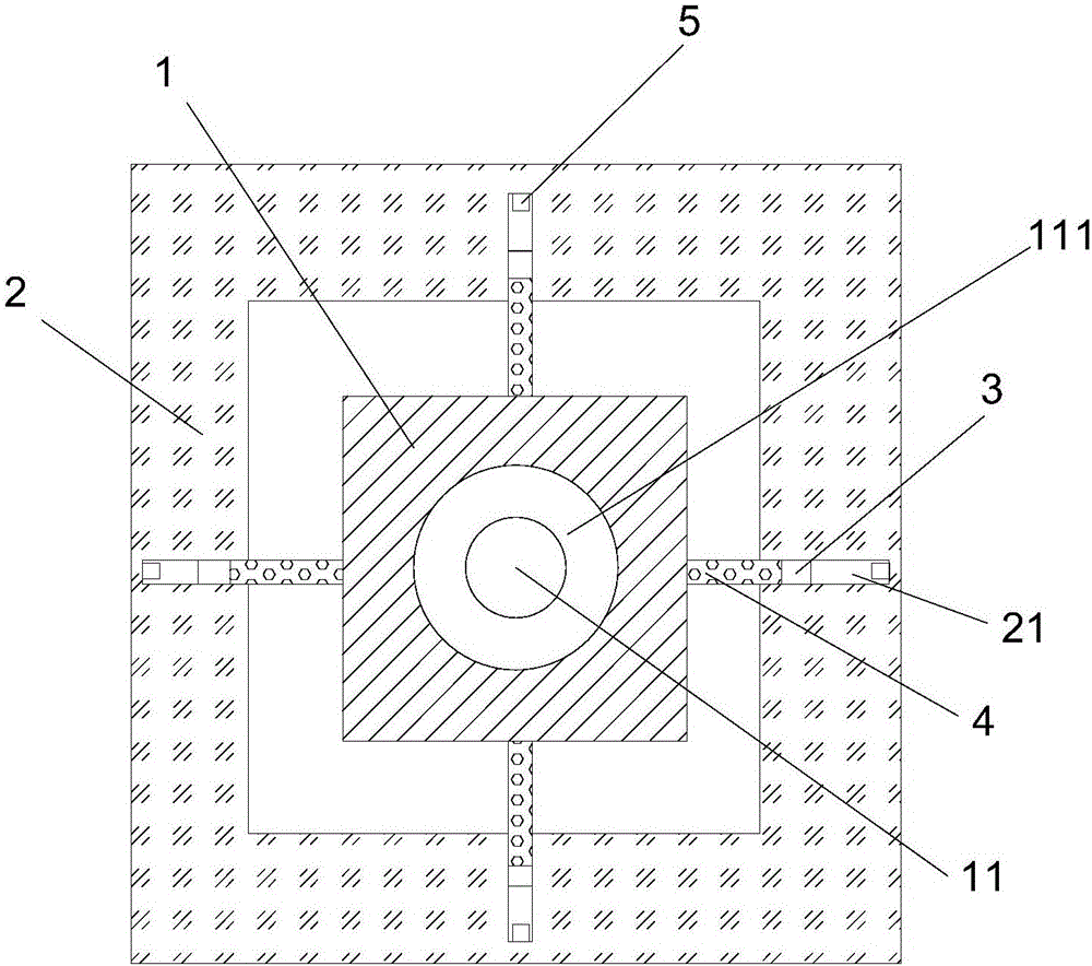
[0024] refer to figure 2 As shown, a practical gear sensor proposed by the present invention includes a moving block 1, a rectangular mounting frame 2, four magnetic parts 3, four detection auxiliary rods 4 and four magnetic sensing elements 5;
[0025] The rectangular mounting frame 2 is located on the outer periphery of the moving block 1, and the four sides of the rectangular mounting frame 2 are provided with sliding grooves 21. The openings of the sliding grooves 21 face the moving block 1, and the four magnetic parts 3 are respectively movable and installed in the four sliding grooves. In 21, the moving direction of the magnetic part 3 is the width direction of the frame edge where the four detection auxiliary rods 4 correspond to the four magnetic parts 3 one by one, and the first ends of the four detection auxiliary rods 4 are connected to the corresponding magnetic parts 3, There are four moving tracks on the moving block 1, and the four moving tracks correspond to t...
PUM
 Abstract
Description
Claims
Application Information
 - R&D
- Intellectual Property
- Life Sciences
- Materials
- Tech Scout
- Unparalleled Data Quality
- Higher Quality Content
- 60% Fewer Hallucinations
Browse by: Latest US Patents, China's latest patents, Technical Efficacy Thesaurus, Application Domain, Technology Topic, Popular Technical Reports.
© 2025 PatSnap. All rights reserved.Legal|Privacy policy|Modern Slavery Act Transparency Statement|Sitemap|About US| Contact US: help@patsnap.com