
Method for reducing peeling risk of photoresist of ion implantation layer

An ion implantation, photoresist technology, used in electrical components, semiconductor/solid-state device manufacturing, circuits, etc.

Active Publication Date: 2017-01-11
SHANGHAI HUALI MICROELECTRONICS CORP
View PDF6 Cites 2 Cited by
  • Summary
  • Abstract
  • Description
  • Claims
  • Application Information

AI Technical Summary

Problems solved by technology

However, there is no report on the use of the three-dimensional structure of the auxiliary pattern of polysilicon devices to reduce the bottom reflection of the photolithography process.

Method used


Image

  • Method for reducing peeling risk of photoresist of ion implantation layer
  • Method for reducing peeling risk of photoresist of ion implantation layer
  • Method for reducing peeling risk of photoresist of ion implantation layer

Examples


specific Embodiment 1

[0042] step one:

[0043] Obtain the design layout of the 45nm technology node active region layer, polysilicon layer, ion implantation layer and all avoidance layers, and mark the allowable addition area in the design layout that allows the addition of polysilicon device auxiliary graphics through logical operations.

[0044] Step two:

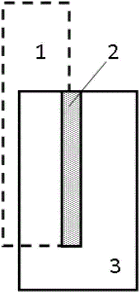
[0045] Automatically find the long side of the ion implantation layer whose length is greater than or equal to 180nm, and then generate a rectangular auxiliary pattern of the original polysilicon device with a width of 40nm and close to the outside of the long side in the allowable addition region.

[0046] Step three:

[0047]Judging the area and the distance between the auxiliary graphics of a single original polysilicon device, marking the area less than 22000nm2 or the distance between each other is less than 100nm and clearing the auxiliary graphics of the original polysilicon device, and the rest is the auxiliary graphics of the polysi...

specific Embodiment 2

[0049] step one:

[0050] Obtain the design layout of the 28nm active region layer, polysilicon layer, ion implantation layer and all avoidance layers, and mark the allowable addition area in the design layout that allows auxiliary graphics of polysilicon devices to be added through logical operations.

[0051] Step two:

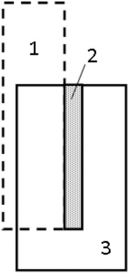
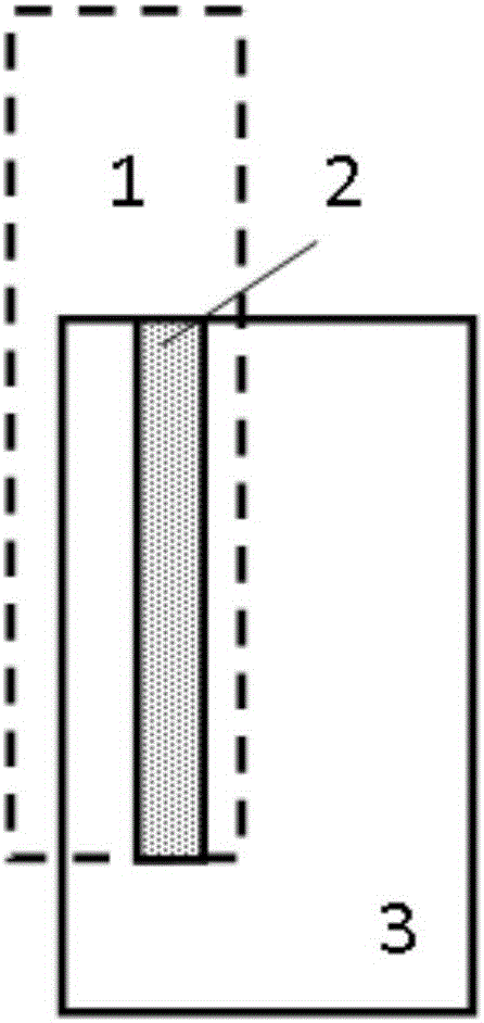
[0052] Automatically find the long side of the ion implantation layer with a length greater than or equal to 144nm, and then generate polysilicon device auxiliary patterns along the long side in the allowable addition area, with a width of 27nm, of which 9nm is within the long side and 18nm is outside the long side.

[0053] Step three:

[0054] Judging the area and the distance between the auxiliary graphics of a single original polysilicon device, marking the area less than 11500nm2 or the distance between each other is less than 100nm and clearing the auxiliary graphics of the original polysilicon device, and the rest is the auxiliary graphics of the pol...


PUM


Abstract

The invention provides a method for reducing the peeling risk of photoresist of an ion implantation layer. The method includes: step 1, obtaining a design layout of an active region layer, a polycrystalline silicon layer, the ion implantation layer and all avoiding layers, and marking allowed adding regions which allow adding of polycrystalline silicon device auxiliary patterns in the design layout through logic operation; step 2, automatically searching long edges of the ion implantation layer, and generating original polycrystalline silicon device auxiliary patterns along the long edges; and step 3, marking and cleaning the original polycrystalline silicon device auxiliary patterns which are not in accordance with a design rule to obtain the expected polycrystalline silicon device auxiliary pattern.

Description

technical field [0001] The invention relates to the field of semiconductor manufacturing, and more specifically, the invention relates to a method for reducing the risk of photoresist stripping of an ion implantation layer. Background technique [0002] With the continuous development of integrated circuit manufacturing technology nodes to smaller critical dimensions, the graphics contained in the integrated circuit design layout are becoming more and more dense, which greatly increases the difficulty of the process and also puts forward higher requirements for the layout design. Ion implantation is an indispensable process for forming semiconductor devices. Before ion implantation, the photoresist will cover the area that does not need to be implanted by photolithography. Once the region is implanted with ions, the function of the semiconductor device will be destroyed, so preventing photoresist stripping is critical for the ion-implanted layer. As the technology node beco...

Claims


Application Information

Patent Timeline
IPC IPC(8): H01L21/266
CPCH01L21/266
Inventor 蒋斌杰于世瑞
Owner SHANGHAI HUALI MICROELECTRONICS CORP
Learn More