Power distribution cabinet with automatic cooling function

A technology for automatic cooling and power distribution cabinets, applied in substation/distribution device casings, electrical components, substation/switch layout details, etc. The effect of high degree, strong practicability and convenient temperature control

Active Publication Date: 2017-01-11
GUANGZHOU KUNKAI MECHANICAL & ELECTRICAL EQUIP CO LTD
View PDF5 Cites 4 Cited by
  • Summary
  • Abstract
  • Description
  • Claims
  • Application Information

AI Technical Summary

Problems solved by technology

[0006] In order to overcome the disadvantages of low automation, inconvenient temperature control and weak practicability in the existing power distribution cabinet, the technical problem to be solv

Method used


Image

  • Power distribution cabinet with automatic cooling function
  • Power distribution cabinet with automatic cooling function
  • Power distribution cabinet with automatic cooling function

Examples


Example Embodiment

[0026] Example 1

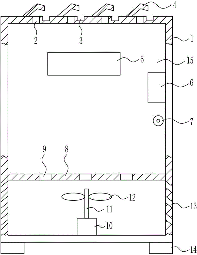
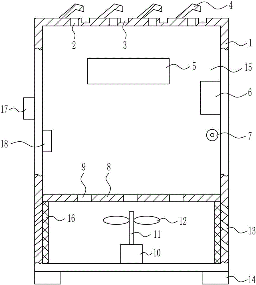
[0027] A power distribution cabinet with automatic cooling function, such as Figure 1-3 As shown, it includes a power distribution cabinet 1, a claw plate 4, a handle 6, a lock 7, a placement plate 8, a rotating motor 10, a rotating rod 11, a blade 12, a tripod 14, a cabinet door 15 and a filter screen 16; The top of the cabinet 1 is evenly provided with first small holes 2, and the left side of the first small hole 2 is provided with a claw plate 4, which is welded and connected to the top of the power distribution cabinet 1, and the top of the power distribution cabinet 1 is evenly opened with The groove 3 is located on the right side of the first small hole 2, and the groove 3 is located directly under the right part of the claw plate 4. The left side of the power distribution cabinet 1 is connected with a cabinet door 15 through a hinge connection. The upper part of 15 has an observation port 5, the upper right part of the cabinet door 15 is welded and co...


PUM


Abstract

The invention relates to a power distribution cabinet, in particular to a power distribution cabinet with an automatic cooling function. The power distribution cabinet comprises a power distribution cabinet body, claw plates, a handle, a lock, a placement plate, a rotating motor, a rotating rod and the like. The claw plates are arranged on left sides of first small holes respectively and connectedly welded to the top of the power distribution cabinet body, the top of the power distribution cabinet body is uniformly provided with grooves positioned on right sides of the first small holes, and the grooves are formed under right portions of the claw plates respectively. The rotating motor can be automatically controlled to operate for cooling the power distribution cabinet when the temperature exceeds a normal operation temperature of devices in the power distribution cabinet, and the rotating motor is automatically controlled to stop after the temperature of the power distribution cabinet is reduced to an appropriate temperature value. The power distribution cabinet with the automatic cooling function has advantages of high automation degree, convenience in temperature regulation and control and high practicality.

Description

technical field [0001] The invention relates to a power distribution cabinet, in particular to a power distribution cabinet with an automatic cooling function. Background technique [0002] Distribution cabinet, a box in which electrical appliances and their wiring are placed to distribute electrical energy. Collectively referred to as the power distribution center. They are centrally installed in the substation of the enterprise, and distribute the electric energy to the lower-level power distribution equipment in different locations. [0003] The power distribution cabinet (box) is divided into power distribution cabinet (box), lighting distribution cabinet (box), metering cabinet (box), and is the final equipment of the power distribution system. The power distribution cabinet is a general term for the motor control center. The power distribution cabinet is used in the occasions where the load is relatively scattered and there are few circuits; the motor control center...

Claims


Application Information

Patent Timeline
IPC IPC(8): H02B1/30H02B1/56H02B1/28
CPCH02B1/28H02B1/306H02B1/565
Inventor 梁钗萍
Owner GUANGZHOU KUNKAI MECHANICAL & ELECTRICAL EQUIP CO LTD
Why Eureka
Try Eureka