Rapid fusing device, rapid fusing control method, DC circuit breaker and control method thereof

A DC circuit breaker and control method technology, applied in the direction of emergency protection circuit devices, electrical components, etc., can solve the problems of slow opening action, reduce the fault removal speed of DC circuit breakers, etc., and achieve the effect of avoiding damage

Active Publication Date: 2017-01-11
XJ ELECTRIC +2
View PDF7 Cites 15 Cited by
  • Summary
  • Abstract
  • Description
  • Claims
  • Application Information

AI Technical Summary

Problems solved by technology

However, the mechanical switch is a key device that determines the time required for the DC circuit breaker to break th

Method used


Image

  • Rapid fusing device, rapid fusing control method, DC circuit breaker and control method thereof
  • Rapid fusing device, rapid fusing control method, DC circuit breaker and control method thereof
  • Rapid fusing device, rapid fusing control method, DC circuit breaker and control method thereof

Examples


Embodiment 1

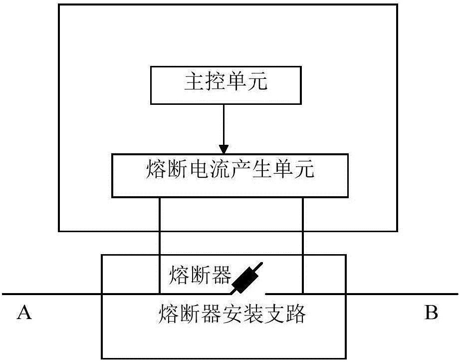
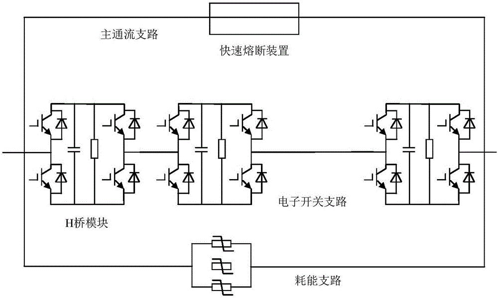
[0044] figure 2 A topological diagram of a DC circuit breaker is given, which includes a main flow branch, an electronic switch branch and an energy consumption branch connected in parallel. Wherein, the main current flow branch includes a fast-fusing device, which includes a fuse installation branch for installing a fuse, and the fuse installation branch is used to be arranged in series in the line; the fast-fuse device also includes a The fusing current generating unit, the two ends of the fusing current generating unit are connected in parallel to the two ends of the fuse installation branch, and are used to output the fusing current to the fuse installation branch; the fast fusing device also includes a main control unit, the main control The unit controls the fusing current generating unit to generate the fusing current. The electronic switching branch includes several series-connected H-bridge modules for assisting the commutation of the main co-current branch. The en...

Embodiment 2

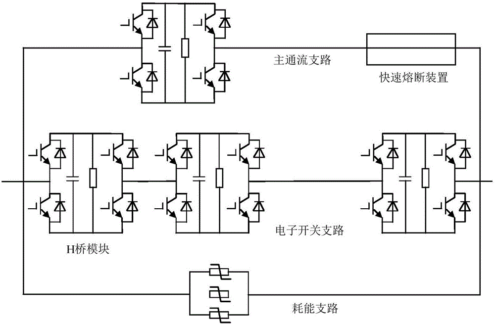
[0047] Such as image 3 As shown, the example is in figure 2 On the basis of , an auxiliary switch module is connected in series with the main flow branch, and the auxiliary switch module is specifically an H-bridge module, which is used to commutate current with the auxiliary electronic switch branch. Similarly, the auxiliary switch module can also be a half-bridge module or a deformed module of the H-bridge module in the prior art, and the number can be more than one.

Embodiment 3

[0049] Such as Figure 4 As shown, the example is in image 3 On the basis of the main flow branch, a mechanical switch is connected in series. After the fuse of the main flow branch is quickly blown, the physical disconnection of the line is realized by turning off the mechanical switch, and the fault is reliably isolated.


PUM


Abstract

The invention relates to a rapid fusing device, a rapid fusing control method, a DC circuit breaker and a control method thereof. The rapid fusing device comprises a fuse installation branch used for installing a fuse, wherein the fuse installation branch is used for being serially arranged in a circuit. The rapid fusing device further comprises a fusing current generation unit, wherein two ends of the fusing current generation unit are connected to two ends of the installation branch in parallel. The rapid fusing device also comprises a main control unit, wherein the main control unit controls the fusing current generation unit to generate fusing current, and the main control unit controls the fusing current generation unit to generate fusing current flowing through the fuse installation branch when the circuit is required to be cut off rapidly so as to enable the fuse to be rapidly blown. The rapid fusing device is applied to a DC circuit breaker, and can realize rapid fault isolation through controlling active blowing of the fuse.

Description

technical field [0001] The invention relates to a fast fusing device and a control method, a DC circuit breaker and the control method, and belongs to the technical field of DC circuit breakers. Background technique [0002] The rapid development of DC transmission technology, especially the multi-terminal DC transmission has unique advantages in forming a strong smart grid, and plays an important role in the control of atmospheric smog and the promotion of social and economic development. However, in the HVDC transmission system, the DC fault ride-through capability is limited. When a line short-circuit fault occurs in the system, the fault current will increase rapidly, which greatly affects the transmission safety. [0003] As a major equipment to ensure the safe operation of the DC transmission system, compared with conventional AC circuit breakers, high-voltage DC circuit breakers are required to operate faster, and usually need to cut off the fault current within a few...

Claims


Application Information

Patent Timeline
IPC IPC(8): H02H7/26
CPCH02H7/262H02H7/268
Inventor 陈同浩李坤雍进玲张锐杨会磊
Owner XJ ELECTRIC
Why Eureka
Try Eureka