
Speed-adjustable coupling machine structure

A technology of coupling and speed regulation, applied in electromechanical devices, electromechanical transmission devices, electrical components, etc., can solve the problems of high cost, complex structure and uneconomical

Inactive Publication Date: 2017-01-11
中兴杰达电能科技股份有限公司
View PDF8 Cites 1 Cited by
  • Summary
  • Abstract
  • Description
  • Claims
  • Application Information

AI Technical Summary

Problems solved by technology

However, the air gap adjustment mechanism 1204 of the existing scheme 2 is not only complicated in structure, expensive in cost, and difficult to maintain, but also increases the volume of the entire mechanical structure during installation, which is quite uneconomical.

Method used


Image

  • Speed-adjustable coupling machine structure
  • Speed-adjustable coupling machine structure
  • Speed-adjustable coupling machine structure

Examples


Embodiment Construction

[0032] In order to make the object, technical solution and advantages of the present invention clearer, the present invention will be further described in detail below in conjunction with the accompanying drawings and embodiments:

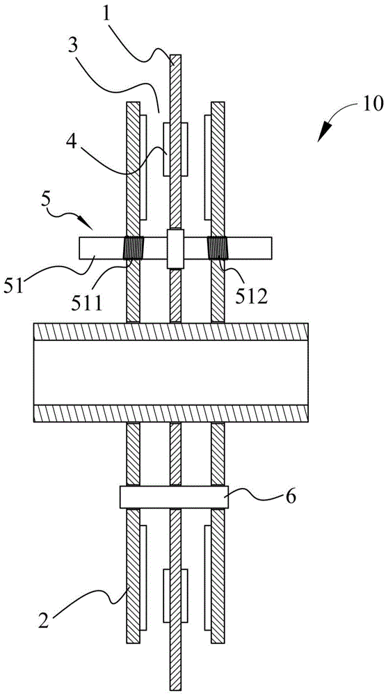
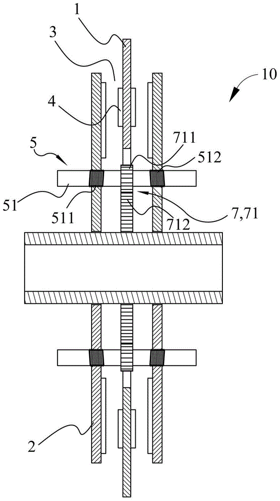
[0033] see figure 1 Shown is the structure of a speed-adjustable shaft coupling 10 according to the present invention, which includes a magnetic turntable 1, and magnetically conductive turntables 2 are coaxially arranged on both sides of the magnetic turntable 1, and the magnetic turntable 1 and the two magnetically conductive turntables There is an air gap 3 between the turntables 2 , and magnetic units 4 are arranged on both sides of the magnetic turntable 1 , so that the magnetic turntable 1 and the two magnetically conductive turntables 2 rotate simultaneously through magnetic linkage.

[0034] The present invention is mainly provided with an air gap adjustment unit 5 between the two magnetically conductive turntables 2, so that the two magne...


PUM


Abstract

The invention relates to a speed-adjustable coupling machine structure. A simple mechanical transmission structure is used for changing magnetic coupling distance of a permanent-magnet coupling machine so as to achieve a function of speed regulation. The speed-adjustable coupling machine structure comprises a magnetic rotary disc, wherein magnetic conduction rotary discs are coaxially arranged at two sides of the magnetic rotary disc, and air gaps are reserved between the magnetic rotary disc and the two magnetic conduction rotary discs; magnetic units are arranged on end surfaces of the two sides of the magnetic rotary disc so that the magnetic rotary disc and the two magnetic conduction rotary discs are in magnetic connection and simultaneously rotate; a protective cover is arranged outside each magnetic unit and is used for preventing the magnetic unit from falling off and being collided; air gap adjustment units are arranged between the two magnetic conduction rotary discs, so that the two magnetic conduction rotary discs get close to or deviate from the magnetic rotary disc to change air gap distances and the relative rotational speed between the magnetic rotary disc and the two magnetic conduction rotary discs are further changed; each air gap adjustment unit comprises a screw rod, the two magnetic conduction rotary discs are arranged at two ends of the screw rod in a penetrating way by threads with opposite rotation directions; and when the screw rod rotates, the two magnetic conduction rotary discs are synchronously driven to get close to or deviate from the magnetic rotary disc by the two threads, and thus, the air gap distances of two sides of the magnetic rotary disc are maintained consistent.

Description

technical field [0001] The invention relates to the structural field of shaft couplings, in particular to a shaft coupling structure that realizes the speed regulation function by means of a simple mechanism. Background technique [0002] The permanent magnet coupling is a device for kinetic energy transmission. It uses magnetic drive to magnetically couple the motor and the load, so as to transmit kinetic energy to drive the load and complete the kinetic energy transmission. [0003] Existing permanent magnetic shaft coupling machine is mainly made up of two parts, the driving disc made of copper or aluminum, and the passive disc with powerful magnets. The driving disc is fixed on the motor shaft, the passive disc is fixed on the load shaft, and there is an air gap between the passive disc and the driving disc. With the magnetic link, the link between the motor and the load will be changed from the original contact link (mechanical hard link) to a non-contact link (magneti...

Claims


Application Information

Patent Timeline
IPC IPC(8): H02K51/00
Inventor 王泓澍杜信谋骆炳江谢嘉伦
Owner 中兴杰达电能科技股份有限公司
Learn More