Output voltage dynamic response optimization control applicable to Vienna rectifier
An output voltage, dynamic response technology, applied in the direction of converting AC power input to DC power output, output power conversion devices, electrical components, etc., can solve problems such as drop, output voltage overshoot, etc.
- Summary
- Abstract
- Description
- Claims
- Application Information
AI Technical Summary
Problems solved by technology
Method used
Image
Examples
Embodiment 1
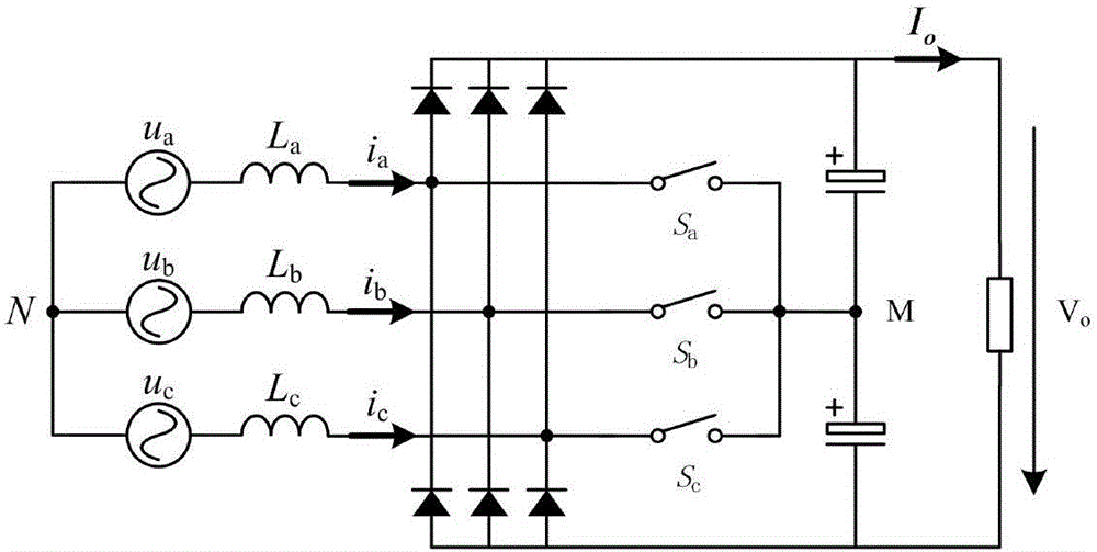
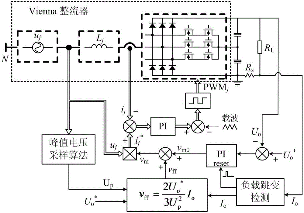
[0059] Picture 1-1 It is a block diagram of the control strategy of the present invention. The hardware circuit topology of the Vienna rectifier of the present invention is as Figure 1-2 It is mainly composed of a power supply, six fast recovery diodes, three boost inductors, three bidirectional power switches, two sets of output capacitors and loads, and is also equipped with a DSP digital controller.
[0060] figure 2 Shown are the control strategy block diagram and load jump detection algorithm of the present invention. In this example, the converter switching frequency and the controller sampling frequency are both 250kHz. This example is suitable for the three-phase input voltage balance situation. For the input voltage three-phase unbalanced The situation can be controlled by existing methods.
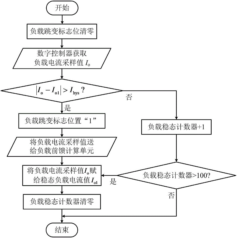
[0061] The flow of the load jump detection algorithm of the present invention is as follows:
[0062] 1) First, the DSP digital controller samples the three-phase input voltage signa...
Embodiment 2
[0075] The dynamic response optimization control method of the output voltage of the Vienna rectifier of the present invention is as follows:
[0076] The hardware circuit topology of Vienna rectifier is as Picture 1-1 , This example is suitable for the three-phase balance of the input voltage.
[0077] The control process of the present invention adopts DSP digital controller (TMS320F2808) as image 3 Shown:
[0078] 1) Initialize the ADC sampling module and ePWM module of the DSP digital controller, and initialize the output voltage reference value U o * It is the target value of output voltage control, the steady-state output current signal is 0, and the three-phase duty cycle d a = 0, d b = 0, d c =0.
[0079] 2) The DSP digital controller enters the ADC interrupt program, performs ADC sampling, and collects the three-phase input voltage signal u a , U b And u c , Three-phase input current signal i a , I b And i c , Output voltage signal u o , Output current signal I o .
[0080] 3...
PUM
 Abstract
Description
Claims
Application Information
 - R&D
- Intellectual Property
- Life Sciences
- Materials
- Tech Scout
- Unparalleled Data Quality
- Higher Quality Content
- 60% Fewer Hallucinations
Browse by: Latest US Patents, China's latest patents, Technical Efficacy Thesaurus, Application Domain, Technology Topic, Popular Technical Reports.
© 2025 PatSnap. All rights reserved.Legal|Privacy policy|Modern Slavery Act Transparency Statement|Sitemap|About US| Contact US: help@patsnap.com


