A rotary engine and its continuous combustion method
A technology of rotating engine and work, applied in combustion engine, machine/engine, internal combustion piston engine, etc., can solve the problems of high noise, low fuel efficiency and complex design of internal combustion engine, and achieve low manufacturing cost, continuous and stable combustion, and simple structure. Effect
- Summary
- Abstract
- Description
- Claims
- Application Information
AI Technical Summary
Problems solved by technology
Method used
Image
Examples
Embodiment 1
[0032] Example 1: Rotary engine.
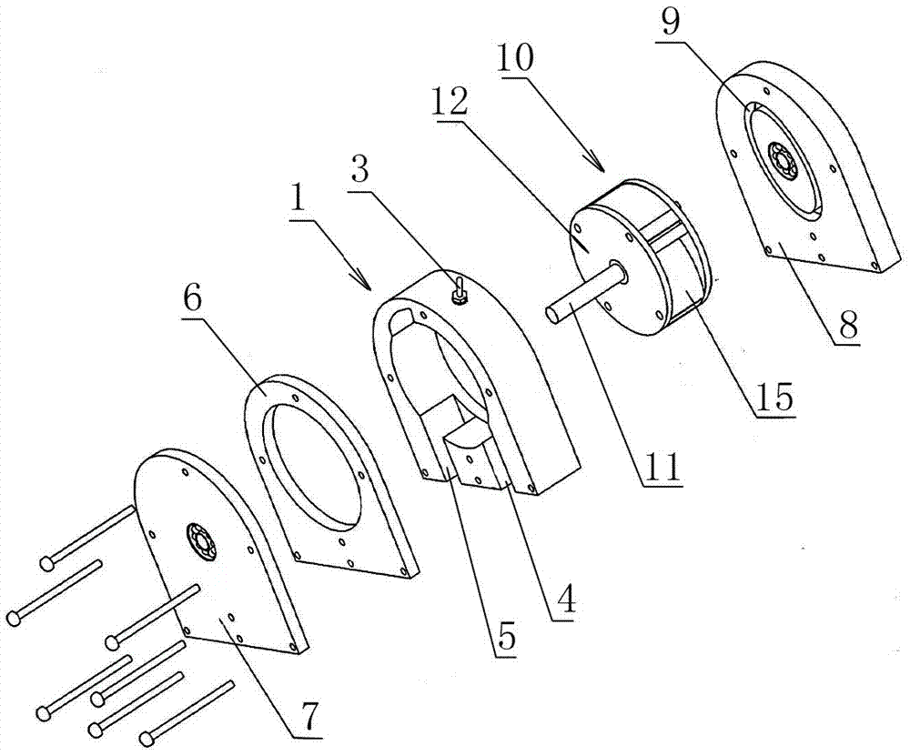
[0033] Such as figure 1 As shown, the present invention mainly includes a cylinder body 1 and a rotor 10 arranged in the cylinder body 1 .
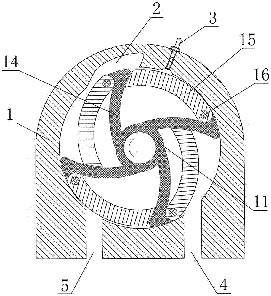
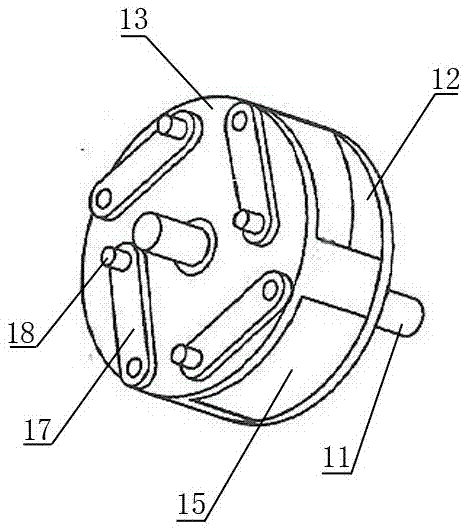
[0034] Cylinder block 1 has a cylindrical inner cavity that runs through front and back, and is used to set rotor 10. A groove communicating with the inner cavity is provided at a position on the left side of the top wall of the inner cavity, as a combustion chamber 2, and the top of the inner cavity A spark plug 3 is provided at the right side of the wall, and the spark plug 3 is located on the right side of the combustion chamber 2, and its end extends into the inner cavity of the cylinder block 1 for igniting the compressed working fluid mixture, and the ignited working fluid The mixed gas enters the combustion chamber 2 for combustion. An air inlet 4 and an exhaust port 5 are provided at the bottom of the cylinder body 1, the air inlet 4 is located on the right side of the exhaust port 5, both of w...
Embodiment 2
[0045] Embodiment 2: The continuous combustion work method of rotary engine.
[0046] Taking the rotary engine with four piston chambers mentioned in Embodiment 1 as an example, the four piston chambers are sorted in counterclockwise order, namely A, B, C, and D, and the method of continuous combustion and work is as follows.
[0047] The initial driving force drives the rotor to rotate counterclockwise in the inner chamber of the cylinder. When the front end of the piston chamber A turns to the position of the air inlet, the piston in it starts to swing into the chamber, and the working medium mixture flows from the air inlet. Enter the piston cavity A, start the intake process, such as Figure 5 As shown in middle I; when the end of the piston chamber A leaves the air inlet, the piston in it swings to the inner dead center, and the air intake process ends.
[0048] Afterwards, the rotor continues to rotate, and the piston in the piston chamber A swings outward from the inne...
PUM
 Abstract
Description
Claims
Application Information
 - R&D
- Intellectual Property
- Life Sciences
- Materials
- Tech Scout
- Unparalleled Data Quality
- Higher Quality Content
- 60% Fewer Hallucinations
Browse by: Latest US Patents, China's latest patents, Technical Efficacy Thesaurus, Application Domain, Technology Topic, Popular Technical Reports.
© 2025 PatSnap. All rights reserved.Legal|Privacy policy|Modern Slavery Act Transparency Statement|Sitemap|About US| Contact US: help@patsnap.com


