Rotary engine and continuous combustion acting method thereof

A technology of rotating engine and work, applied in combustion engine, machine/engine, internal combustion piston engine, etc., can solve the problems of high noise, low fuel efficiency and complex design of internal combustion engine, and achieve low manufacturing cost, continuous and stable combustion, and simple structure. Effect

Active Publication Date: 2017-01-18
狄庆会
View PDF6 Cites 0 Cited by
  • Summary
  • Abstract
  • Description
  • Claims
  • Application Information

AI Technical Summary

Problems solved by technology

[0004] One of the objects of the present invention is to provide a rotary engine to solve the problems of existing internal combustion engines such as high noise, high emission, low fuel efficiency, complex design and high cost

Method used


Image

  • Rotary engine and continuous combustion acting method thereof
  • Rotary engine and continuous combustion acting method thereof
  • Rotary engine and continuous combustion acting method thereof

Examples


Embodiment 1

[0032] Example 1: Rotary engine.

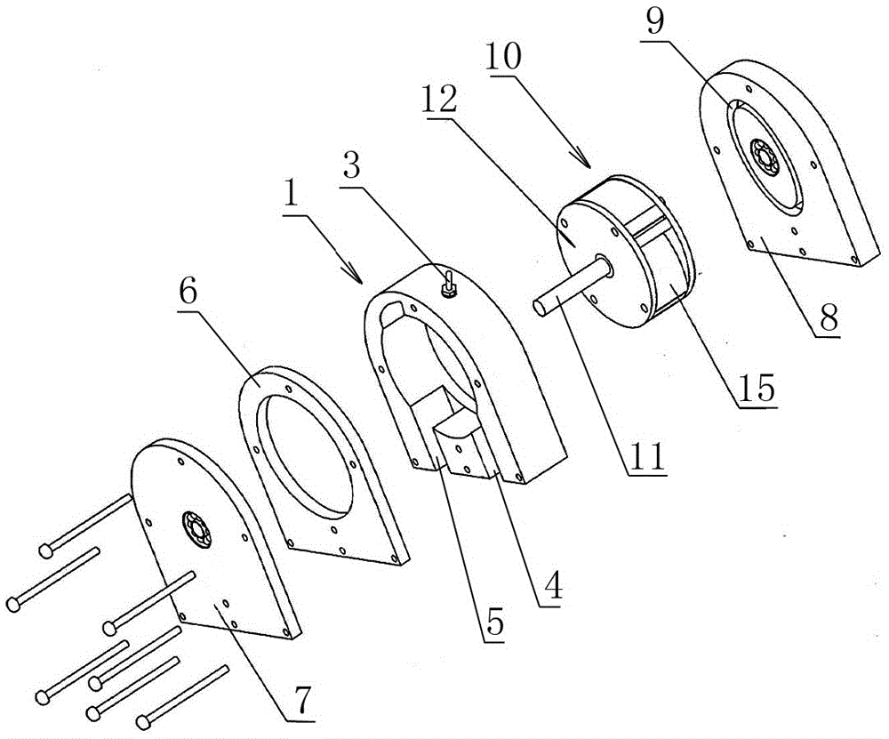
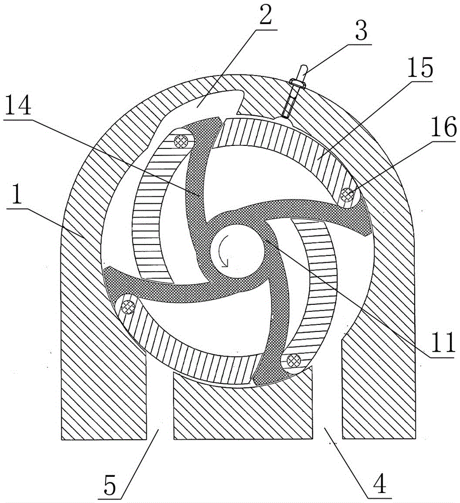
[0033] Such as figure 1 As shown, the present invention mainly includes a cylinder body 1 and a rotor 10 arranged in the cylinder body 1 .

[0034] Cylinder block 1 has a cylindrical inner cavity that runs through front and back, and is used to set rotor 10. A groove communicating with the inner cavity is provided at a position on the left side of the top wall of the inner cavity, as a combustion chamber 2, and the top of the inner cavity A spark plug 3 is provided at the right side of the wall, and the spark plug 3 is located on the right side of the combustion chamber 2, and its end extends into the inner cavity of the cylinder block 1 for igniting the compressed working fluid mixture, and the ignited working fluid The mixed gas enters the combustion chamber 2 for combustion. An air inlet 4 and an exhaust port 5 are provided at the bottom of the cylinder body 1, the air inlet 4 is located on the right side of the exhaust port 5, both of w...

Embodiment 2

[0045] Embodiment 2: The continuous combustion work method of rotary engine.

[0046] Taking the rotary engine with four piston chambers mentioned in Embodiment 1 as an example, the four piston chambers are sorted in counterclockwise order, namely A, B, C, and D, and the method of continuous combustion and work is as follows.

[0047] The initial driving force drives the rotor to rotate counterclockwise in the inner chamber of the cylinder. When the front end of the piston chamber A turns to the position of the air inlet, the piston in it starts to swing into the chamber, and the working medium mixture flows from the air inlet. Enter the piston cavity A, start the intake process, such as Figure 5 As shown in middle I; when the end of the piston chamber A leaves the air inlet, the piston in it swings to the inner dead center, and the air intake process ends.

[0048] Afterwards, the rotor continues to rotate, and the piston in the piston chamber A swings outward from the inne...


PUM


Abstract

The invention relates to a rotary engine and a continuous combustion acting method thereof. As for the structure, the rotary engine comprises a cylinder body and a cylindrical rotor arranged in an inner cavity of the cylinder body. The cylinder body is provided with an air inlet and an air outlet, and the air inlet and the air outlet communicate with the inner cavity. A groove serving as a combustor is further formed in the inner wall of the inner cavity of the cylinder body. A sparking plug is arranged on the portion, beside the groove, of the cylinder body. The rotor is provided with four piston cavities in the same shape and with the equal dimensions. Each piston cavity is internally provided with an arc plate-shaped piston, and the piston can make internal swinging motion in the piston cavity. While the rotor rotates by a circle, each piston swings back and forth twice in the corresponding piston cavity, and the working process of air intake, compression, ignition, pushing the last piston to act, and exhausting is completed correspondingly. According to the rotary engine and the continuous combustion acting method thereof, combustion of working media is continuous and stable, the combustion rate is high, the output power is large, the power density is high, hazard waste emission is low, fuel economy performance is high, the torque angle of the largest explosion pressure is good, running is smooth and stable, vibration is small, noise is low, and thermal efficiency is high.

Description

technical field [0001] The invention relates to a rotary engine and its working method, in particular to a rotary engine and its continuous combustion method. Background technique [0002] The reciprocating piston internal combustion engine occupies a leading position in the power field of the world today, and it is widely used as a vehicle power. However, the further development of the internal combustion engine is greatly restricted because of its own complex structural characteristics. The reciprocating inertial force and moment of inertia caused by the reciprocating motion of the piston group of the reciprocating piston internal combustion engine cannot be completely balanced, and this inertial force increases according to the square of the rotational speed. When the rotational speed increases, the inertial load acting on the bearing and some The stress of the parts increases significantly, and the vibration and noise caused by the unbalanced force further deteriorate, s...

Claims


Application Information

Patent Timeline
IPC IPC(8): F02B55/08F02B55/02F02B53/02
CPCF02B53/02F02B55/02F02B55/08Y02T10/12
Inventor 狄庆会
Owner 狄庆会
Why Eureka
Try Eureka