
Auxiliary cooperative vehicle infrastructure driving system and method

A technology for assisted driving and vehicle-road coordination, applied in the field of intelligent transportation, it can solve the problems of large impact on detection accuracy, unstable signal strength, and inability to guarantee positioning accuracy, so as to avoid positioning failures or errors.

Active Publication Date: 2017-01-18
BEIJING WANJI TECH
View PDF5 Cites 84 Cited by
  • Summary
  • Abstract
  • Description
  • Claims
  • Application Information

AI Technical Summary

Problems solved by technology

Although the vehicle-based terminal based on GPS can accurately locate the vehicle position and obtain the location information of surrounding vehicles through vehicle-to-vehicle communication (V2V) or vehicle-to-road communication (V2R), the coverage of GPS signals is limited and cannot be used indoors, in tunnels or near tall buildings. Ensure a stable communication connection, and cannot detect the driving state of non-motorized vehicles and pedestrians at complex intersections; roadside-based video detection equipment can obtain vehicle information, pedestrian information, and traffic light information at intersections through video recognition methods, but the collection The accuracy and real-time performance of the information obtained are poor, and the detection accuracy is greatly affected by ambient light and background light
The signal strength of the on-board unit in the dedicated short-range communication technology can also be used to achieve positioning, but due to the interference of factors such as unstable signal strength, surrounding environment occlusion and reflection, and attenuation and absorption of body materials, its positioning accuracy cannot be guaranteed in the actual environment.

Method used


Image

  • Auxiliary cooperative vehicle infrastructure driving system and method
  • Auxiliary cooperative vehicle infrastructure driving system and method

Examples


Embodiment Construction

[0034] Embodiments of the present invention are described in detail below, examples of which are shown in the drawings, wherein the same or similar reference numerals designate the same or similar elements or elements having the same or similar functions throughout. The embodiments described below by referring to the figures are exemplary only for explaining the present invention and should not be construed as limiting the present invention.

[0035] In the following description, many specific details are set forth in order to fully understand the present invention. However, the present invention can also be implemented in other ways different from those described here. Therefore, the protection scope of the present invention is not limited by the specific details disclosed below. EXAMPLE LIMITATIONS.

[0036] Those skilled in the art can understand that, unless otherwise defined, all terms (including technical terms and scientific terms) used herein have the same meaning as c...


PUM


Abstract

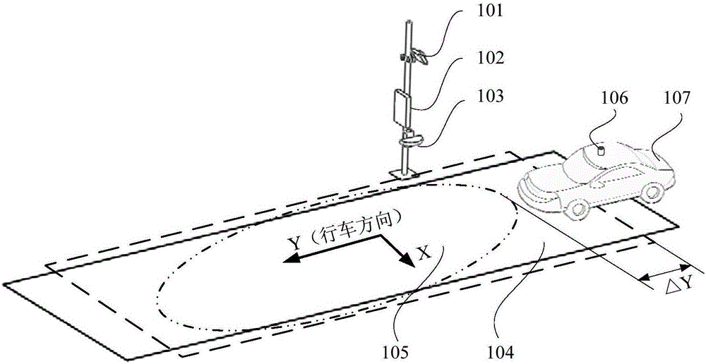
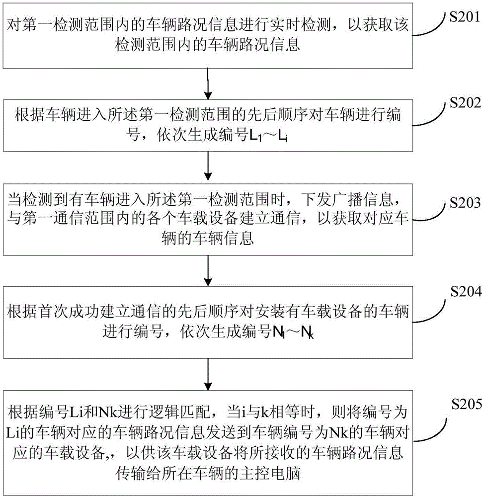
The invention relates to an auxiliary cooperative vehicle infrastructure driving system and a method. The system comprises road side equipment and vehicle equipment, wherein the road side equipment comprises a laser detection module, a communication module and a road side main control module, the vehicle equipment is mounted on vehicles and is connected with a vehicle computer, the laser detection module is used for detecting objects in a first detection scope to acquire the vehicle road condition information of each vehicle in the detection scope and transmitting the information to the road side main control module, the road side main control module is used for determining the vehicle road condition information corresponding to each vehicle, communicating with each vehicle equipment in a first communication scope through the communication module and transmitting the vehicle road condition information to the vehicle equipment of the corresponding vehicles, and the vehicle equipment is used for transmitting the received vehicle road condition information to respective corresponding main control computers. Through the system and the method, the precise road condition information can be provided for automatic driving vehicles or auxiliary driving vehicles, and data support is provided for path planning and pass strategies of the vehicles.

Description

technical field [0001] The invention relates to the technical field of intelligent transportation, in particular to a vehicle-road cooperative driving assistance system and method. Background technique [0002] With the continuous development of assisted driving and automatic driving technology, the supporting vehicle-road cooperative assisted driving system has received more and more attention. A comprehensive vehicle-road collaborative assisted driving system can not only provide vehicles with information such as location, distance, and speed, but also provide vehicles with traffic meeting / following warnings, red street light information, and pedestrian traffic detection for vehicles at complex traffic intersections. However, the technical solutions of the current vehicle-road cooperative driving assistance system are mostly GPS-based vehicle-mounted terminals or roadside-based video detection equipment. Although GPS-based vehicle-mounted terminals can accurately locate t...

Claims


Application Information

Patent Timeline
IPC IPC(8): G08G1/0968G08G1/0967G08G1/08G08G1/04
CPCG08G1/04G08G1/08G08G1/096783G08G1/096811
Inventor 胡攀攀房颜明李媛媛赵强李谋辉蒋难得夏思斌
Owner BEIJING WANJI TECH
Learn More