Scattered-radiation collimator and method for producing a scattered radiation collimator

A technology of scattered radiation, manufacturing method, applied in the direction of using aperture/collimator, radiation/particle processing, instruments used for radiological diagnosis, etc., can solve problems such as formation of cracks, increased mechanical stress of scattered radiation collimator, etc., Achieve the effect of preventing buckling, avoiding artifacts, and avoiding wrong positioning

Inactive Publication Date: 2011-06-22
SIEMENS AG
View PDF4 Cites 10 Cited by
  • Summary
  • Abstract
  • Description
  • Claims
  • Application Information

AI Technical Summary

Problems solved by technology

However, a disadvantage of this scattered radiation collimator is, inter alia, that there is a risk of cracks forming at the joints between adjacent scattered radiation collimators, which are necessarily present due to the tile-like structure, thus making it possible for the scattered radiation to reach the detector element
[0007] In addition, the mechanical stress of future scattered radiation collimators is also increased

Method used


Image

  • Scattered-radiation collimator and method for producing a scattered radiation collimator
  • Scattered-radiation collimator and method for producing a scattered radiation collimator
  • Scattered-radiation collimator and method for producing a scattered radiation collimator

Examples


Embodiment Construction

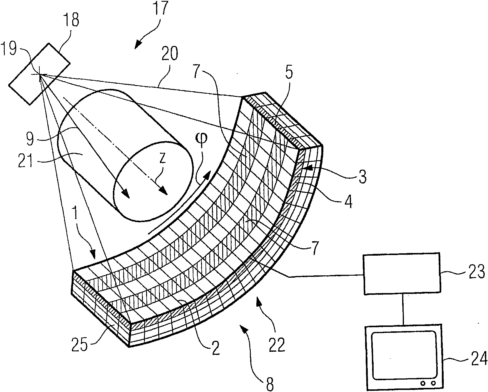
[0038] exist figure 1 A computed tomography system 17 is shown in FIG. 2 , which comprises a radiation source 18 in the form of an x-ray tube, from which a focal point 19 of the radiation source 18 emits an x-ray fan 20 . The X-ray fan 20 passes through an object 21 or patient to be examined and reaches a radiation detector 22, here an X-ray detector.

[0039] The X-ray tube 18 and the X-ray detector 22 are arranged opposite each other on a frame (not shown here) of the computed tomography apparatus 17, which can be placed on direction about the system axis Z (=patient axis) of the computed tomography device 17 . The direction thus denotes the circumferential direction of the gantry, and the Z direction denotes the longitudinal direction of the object 21 to be inspected.

[0040] During operation of the computed tomography device 17 , the x-ray tube 18 and the x-ray detector 22 arranged on a gantry rotate around the object 21 , wherein the x-rays of the object 21 are taken...


PUM


Abstract

A scattered-radiation collimator is disclosed for radiological radiation with a multiplicity of absorber elements that are arranged one behind the other in a collimation direction and held in a support frame. In at least one embodiment, the support frame includes a holding device for holding the absorber elements on opposite sides across the collimation direction, and at least one strip-like holding element spans the absorber elements in a collimation direction on the radiation entry side and/or the radiation exit side of the scattered-radiation collimator and additionally fixes the absorber elements on the longitudinal edges thereof in a mechanical fashion. In at least one embodiment, the holding elements prevent deformations of long absorber elements caused by centrifugal forces to a large extent. This affords the possibility of implementing scattered-radiation collimators with a large Z-coverage that meet the demand on the absorber elements in respect of dimensional stability and positional accuracy. Moreover, at least one embodiment of the invention relates to a method for producing such a scattered-radiation collimator.

Description

technical field [0001] The invention relates to a scattered radiation collimator for radioactive radiation and to a method for the production of such a scattered radiation collimator. Background technique [0002] Especially in tomography systems, for example in computed tomography systems, it is known that scattering leads to an influence on the image quality. In order to reduce the detected scattered radiation component in the detector signal, a so-called scattered radiation collimator is connected upstream of the radiation detector of the computed tomography system. [0003] Known scattered radiation collimators comprise, for example, non-reciprocal absorber elements arranged side by side in the collimation direction with respect to their longitudinal extension. The absorber surface sector of the absorber element is radially aligned with the focus of the radiation source, so that only radiation from the spatial direction aligned with the focus can reach the radiation det...

Claims


Application Information

Patent Timeline
Patent Type & Authority Applications(China)
IPC IPC(8): A61B6/03G21K1/02
CPCA61B6/4291A61B6/032G21K1/025Y10T29/49826
Inventor 克劳斯・波汉
Owner SIEMENS AG
Why Eureka
Try Eureka