Automatic lumbar fixed-point spinning reduction machine
A fixed-point rotation and reset machine technology, applied in the field of medical devices, can solve the problems of insignificant treatment effect, single traction form, and inaccurate control, and achieve self-adjustment and adaptation, increase the range of activities, and overcome the small angle. Effect
- Summary
- Abstract
- Description
- Claims
- Application Information
AI Technical Summary
Problems solved by technology
Method used
Image
Examples
Embodiment (1)
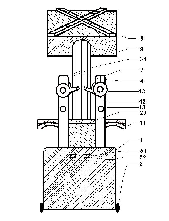
[0018] Embodiment (1): such as figure 2 As shown, it can be seen from the actual view of the whole lumbar spine rotary reset machine that the present invention mainly consists of a chair body (1), a back fixator (2), wheels (3), a thigh pressing plate fixing device (11), and a span fixing device (29). , movable rod (7), chest rest board (8), and upper chest and back straps (9). Before treatment, press the back shift switch (52) to make the back fixer (2) back to a proper position , and then the patient faces the back fixer (2), straddles the chair body (1) between the straddle fixation device (29) and the back fixer (2), and keeps the foot and calf, calf and thigh All into a 90-degree posture, adjust the two thigh compression device lifting knobs (14) on the thigh compression device (11), so that the patient's two thighs can be conveniently placed on the thigh compression device (11) and the cross fixation between the device (29), and then the inner side of the thigh is clos...
Embodiment (2)
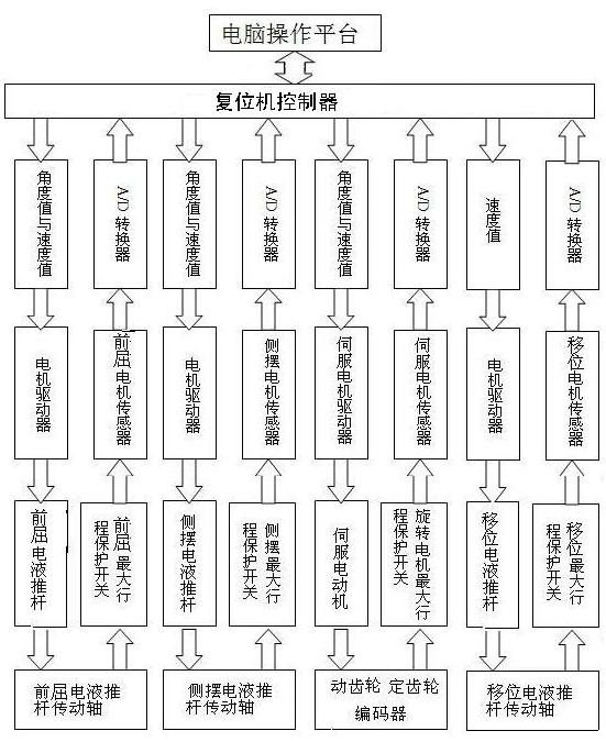
[0019] Embodiment (2): such as figure 2 As shown, the movable rod (7) is mainly composed of four parts, which are the movable rod height adjustment knob (15), the movable rod height adjustment inner shaft (6), the movable rod height adjustment outer shaft (5), and the movable rod forward bending Paragraph (34). There are three main actions of the movable rod (7). The first movement is forward bending. The active fulcrum 1 (31), the forward-bending electro-hydraulic push rod machine (22) drives the forward-bending electro-hydraulic push rod machine drive shaft (25 ) to move forward, and then the movable rod (7) can use the movable fulcrum 1 (31) as the fulcrum to realize forward leaning, through the sensor (23) of the forward-bending electro-hydraulic push rod machine and the maximum stroke protection switch of the forward-bending electro-hydraulic push rod machine (24) and other devices detect the state of the push rod of the forward-bending electro-hydraulic push rod machi...
Embodiment (3)
[0020] Embodiment (3): such as Figure 4 As shown, the back holder is mainly composed of the back holder height adjustment lever (4), the back holder lifting knob (15), the model hand (42), the plastic kit (43), the spring (44), the sleeve rod (45), The stuck point (46) consists of seven parts. One end of the sleeve rod (45) is fixed to the model hand (42), the other end covers the spring (44), and one end of the spring (44) is fixed through the clamping point (46), and the other end of the spring (44) is passed The plastic kit (43) is fixed, so that the model hand (42) has elasticity and can be stretched, so that it can follow a certain place of the patient's lumbosacral at any time under the situation of different forces, and keep the precise fixation on this place, and at the same time played a buffer role. One end of the adjustment shaft (16) of the back fixer is connected with the displacement electro-hydraulic push rod machine (16), and the other end is welded and fixe...
PUM
 Abstract
Description
Claims
Application Information
 - R&D
- Intellectual Property
- Life Sciences
- Materials
- Tech Scout
- Unparalleled Data Quality
- Higher Quality Content
- 60% Fewer Hallucinations
Browse by: Latest US Patents, China's latest patents, Technical Efficacy Thesaurus, Application Domain, Technology Topic, Popular Technical Reports.
© 2025 PatSnap. All rights reserved.Legal|Privacy policy|Modern Slavery Act Transparency Statement|Sitemap|About US| Contact US: help@patsnap.com


