Connected cavity based phased array antenna

A phased array antenna and connecting cavity technology, applied in the field of radar technology, can solve the problems of increasing the size of the antenna system, complex feeding network design, high cross-section and difficult integration conformality, etc., to achieve simple structure, convenient processing and assembly, and avoid feeding The effect of electrical network design

Active Publication Date: 2017-01-18
UNIV OF ELECTRONIC SCI & TECH OF CHINA
View PDF4 Cites 12 Cited by
  • Summary
  • Abstract
  • Description
  • Claims
  • Application Information

AI Technical Summary

Problems solved by technology

Therefore, the feed network of strongly coupled dipole arrays is complex and bulky, increasing the size, weight and cost of the overall antenna system
In addition, in order to avoid backward radiation, the floor is usually placed at a distance of a quarter wavelength (near the high frequency band) from the front, plus a wide-angle impedance matching layer placed above the front to expand the scanning angle range (usually by Several layer thicknesses, dielectric substrates with different dielectri

Method used


Image

  • Connected cavity based phased array antenna
  • Connected cavity based phased array antenna
  • Connected cavity based phased array antenna

Examples


Example Embodiment

[0024] Example 1

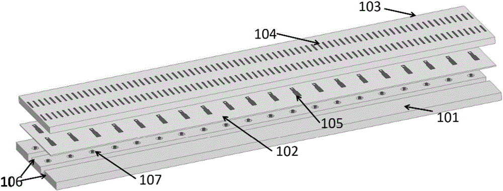
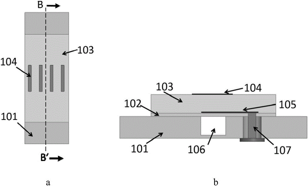
[0025] The wide-bandwidth angular scanning phased array antenna based on the connection cavity of this embodiment adopts a 20×2 planar array form, such as figure 1 As shown, it is divided into three layers, including a lower floor 101 with a metal cavity connected, a middle dielectric substrate 101 printed with a microstrip feeder 105, and an upper dielectric substrate 103 printed with a metal patch 104. The lower metal floor 101 is an aluminum plate with a thickness of 3.5 mm. A rectangular section cavity 106 with a depth of 3 mm and a width of 4 mm is processed on the aluminum plate, and the cavity is not filled with medium. The intermediate dielectric substrate 102 has a relative dielectric constant of 2.2, a thickness of 0.5 mm, and a microstrip feeder 105 printed on it. The upper dielectric substrate 103 has a relative dielectric constant of 2.2, a thickness of 3 mm, and a rectangular patch 104 printed on it. The inner core 107 of the microwave coaxial c...

Example Embodiment

[0028] Example 2

[0029] Specifically, each basic antenna unit is separately extended in two dimensions to form Figure 5 Medium 9×9 planar array. The other structure is the same as the detailed description in Embodiment 1.

Example Embodiment

[0030] Example 3

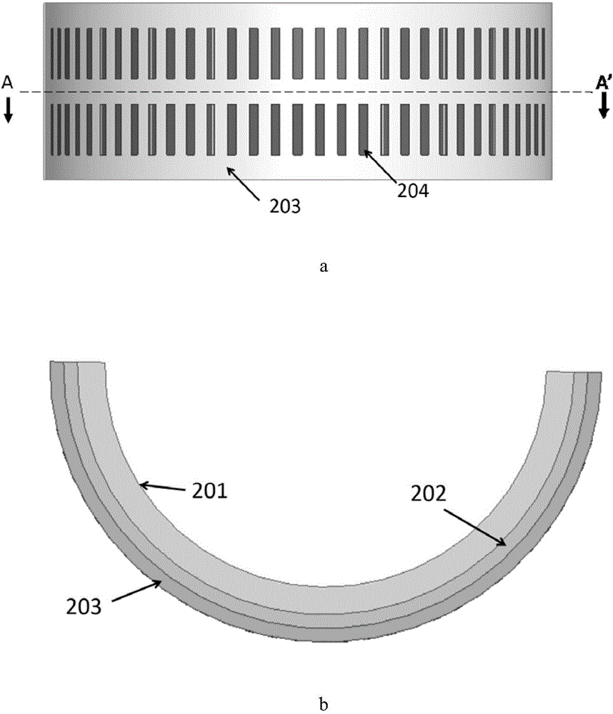
[0031] Figure 7 This is the basic antenna unit structure for dual polarization radiation in this embodiment. As shown in the figure, it is divided into four layers, including a lower floor 701 with a metal cavity connected, a middle dielectric substrate 702 printed with microstrip feed lines 707 and 708, an upper dielectric substrate 703 printed with a metal patch 706, and a metal patch printed with Sheet 705 is the second upper dielectric substrate 704. The inner cores 709 and 710 of the microwave coaxial connector pass through the openings on the lower metal floor 701 and are respectively connected to the orthogonally placed microstrip feeders 707 and 708 for feeding to form dual polarization. The metal patches 705 and 706 are placed orthogonal to each other. Figure 8 It is a schematic diagram of the lower floor structure of a 9x9 planar array using the basic antenna unit. Such as Figure 8 As shown, the floor has long grooves staggered horizontally and...


PUM

PropertyMeasurementUnit
Thicknessaaaaaaaaaa
Thicknessaaaaaaaaaa

Abstract

The invention belongs to the technical field of radar technology and wireless communication, in particular to a connected cavity based phased array antenna. The phased array antenna is formed by basic antenna units in matrix array arrangement with each basic antenna unit comprising a long grooved metal floor. The metal floor is covered with a middle layer dielectric substrate, whose surface is printed with a microstrip feed line. The middle layer dielectric substrate is provided with an upper layer dielectric substrate, whose surface is printed with a metal paster. Through the coaxial connector core, the phased array antenna crosses the through hole on the lower metal floor and the corresponding through hole on the middle layer dielectric substrate to be in connected with the microstrip feed line to feed. The metal paster, as a radiation structure, constitutes a wide-angle impedance matching layer with the upper dielectric substrate, which ensures that the array has largest angle scanning capability when it is in the working bandwidth. The feeding system is simple, the low profile is easy to conform, and the processing and assembling is convenient, making the arrayed antenna used in radar and communication system requiring wide range and large angle scanning range.

Description

technical field [0001] The invention belongs to the field of radar technology and wireless communication technology, in particular to a phased array antenna based on a connection cavity, in particular to wide-band and wide-angle scanning, and is suitable for radar and communication systems such as microwaves and millimeter waves. Background technique [0002] Over the past few decades, broadband, wide-angle scanning phased array antennas have received widespread attention in the military and commercial fields, and are often used in systems such as broadband radar, satellite communications, and radio astronomy. The demand for multifunctional (surveillance, identification, and target tracking) systems on military airborne platforms has also promoted the development of broadband, wide-angle phased array antennas. In this application, small space and light weight are the main constraints in antenna design, so it is very beneficial to achieve broadband and wide-angle scanning und...

Claims


Application Information

Patent Timeline
IPC IPC(8): H01Q21/00H01Q21/24H01Q1/48H01Q1/50
CPCH01Q1/48H01Q1/50H01Q21/0075H01Q21/24
Inventor 屈世伟夏润梁张力维李鹏发陈益凯杨仕文
Owner UNIV OF ELECTRONIC SCI & TECH OF CHINA
Why Eureka
Try Eureka