Supercharge Your Innovation With Domain-Expert AI Agents!

Feeding device and electrical junction box

A technology of a power feeding device and an electrical junction box, which is applied in the field of power feeding devices, can solve problems such as waste, and achieve the effects of reducing waste, reducing rated current and realizing redundancy.

Inactive Publication Date: 2017-01-18
YAZAKI CORP
View PDF7 Cites 0 Cited by
  • Summary
  • Abstract
  • Description
  • Claims
  • Application Information

AI Technical Summary

Problems solved by technology

Therefore, the problem of wasting

Method used


Image

  • Feeding device and electrical junction box
  • Feeding device and electrical junction box

Examples


Embodiment Construction

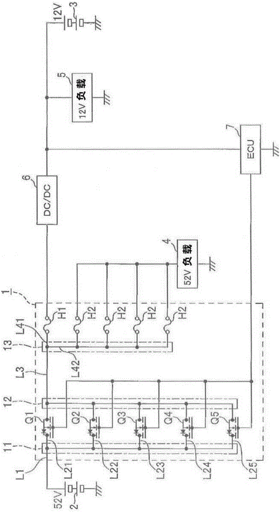
[0028] In the following, reference will be made to figure 1 The power supply box (feeding device, electrical junction box) of the present invention will be described. The power supply box 1 of the present invention is connected to an on-vehicle battery and a load, and is configured to supply power from the battery to the load.

[0029] In the vehicle on which the power supply box 1 of one embodiment of the present invention is installed, two batteries, a 52V battery 2 (power source) and a 12V battery 3, are installed, and a 52V load 4 (load) driven by 52V and a 12V battery driven by 12V are arranged. Drive 12V load 5(LOAD).

[0030] Such as figure 1 As shown, the power supply box 1 has a branch circuit 11, a combining circuit 12, a branch circuit 13, MOSFETs Q1-Q5 (switching units) and fuses H1, H2.

[0031] The branch circuit 11 is a circuit for branching the supply path L1 of the 52V battery 2 into five (=n) branch paths L21-L25. The combining circuit 12 is a circuit f...


PUM


Abstract

The invention provides a feeding device and an electrical junction box. According to the invention, a power-supply unit and an electric junction b are provided. A branch circuit branches a supply route of a 52V-battery into a (n is an integer of 3 or more) branch routes. A merge circuit joins the n branch routes to one supply route. MOSFETs are arranged on the n branch routes respectively. A rated current of each of the MOSFET is equal to or larger than a rated current of loads (12V-load, 52V-load, ECU, and 12V-battery) which are supplied with electric power from the supply route divided by n-1 and less than the rated current divided by n-2.

Description

technical field [0001] The invention relates to a power feeding device and an electric junction box. Background technique [0002] In a vehicle, a power feeding device is arranged for supplying electric power from a battery to a load. The power feeding device is provided with a switch for turning on / off power supply to the load between the load and the battery. In such a power feeding device, even if the electronic components of the power feeding device are damaged, stable power supply is required, so as to continuously supply power to the load. For example, in Patent Document 1, a spare driver for controlling switches is provided (see Patent Document 1). [0003] In addition, in order to continue supplying power to the load even if the switch is damaged, settings such as figure 2 The supply system shown. exist figure 2 Among them, the power feeding device 100 has: a branch point circuit 102, which branches the supply path L10 from the 52V battery into two branch paths ...

Claims


Application Information

Patent Timeline
Patent Type & Authority Applications(China)
IPC IPC(8): H02J7/00H02G3/08H02H3/08
CPCH02G3/08H02H3/08H02J7/0063H02J2207/20H02J7/00304B60R16/03H02J1/08H02J2310/46
Inventor 上园浩一木下幸佑户田隆文
Owner YAZAKI CORP
Features
  • R&D
  • Intellectual Property
  • Life Sciences
  • Materials
  • Tech Scout
  • Unparalleled Data Quality
  • Higher Quality Content
  • 60% Fewer Hallucinations
Learn More