Supercharge Your Innovation With Domain-Expert AI Agents!

Fuse wiring structure and wiring method thereof

A wiring structure and fuse technology, which is applied in the direction of electrical component structure association, transformer/inductor coil/winding/connection, etc., can solve the problems of aggravating the aging and decomposition of transformer oil inside the box transformer, unfavorable box transformer stable operation, etc., to avoid The effect of overheating of the fuse, reducing the cost of the box and improving the stability

Pending Publication Date: 2022-01-28
广州骏发电气设备有限公司
View PDF0 Cites 0 Cited by
  • Summary
  • Abstract
  • Description
  • Claims
  • Application Information

AI Technical Summary

Problems solved by technology

However, as the current wind power American-style box-type transformer capacity gradually develops toward larger capacity, the rated current of the fuse will become larger and larger. At the phase line, the heat generated when the rated line current passes through the fuse is greater, and the fuse is located inside the oil tank of the box-type transformer. Overheating of the fuse will aggravate the aging and decomposition of the transformer oil inside the box-type transformer, which is not conducive to the stable operation of the box-type transformer

Method used


Image

  • Fuse wiring structure and wiring method thereof
  • Fuse wiring structure and wiring method thereof
  • Fuse wiring structure and wiring method thereof

Examples


Embodiment 1

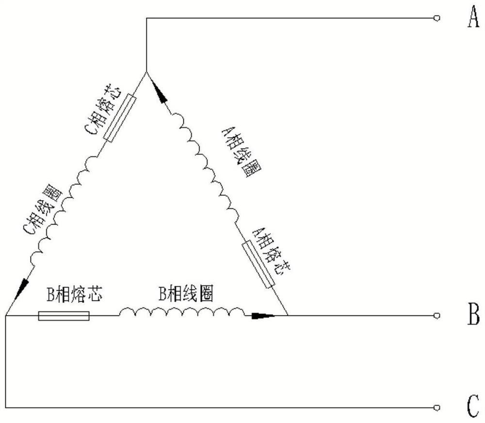
[0026] This embodiment provides a fuse wiring structure, such as image 3 As shown, it includes three-phase transformer coils. The three-phase transformer coils include A-phase coils, B-phase coils, and C-phase coils connected end to end in sequence. The three-phase transformer coils are connected in a delta, and the combination of adjacent two-phase transformer coils The points are drawn as the three phase lines of the three-phase transformer; the fuse wiring structure also includes A-phase fuses, B-phase fuses and C-phase fuses connected in series with the A-phase coil, B-phase coil and C-phase coil respectively .

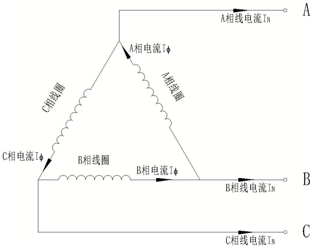
[0027] This embodiment can reduce the rated current of the fuse, reduce the cost of the box-type transformer, and facilitate the stable operation of the box-type transformer. Specifically, such as figure 1 shown in I Φ Indicates the phase current (referring to the current flowing through each phase coil in the three-phase transformer), expressed in I N Indica...

Embodiment 2

[0038] This embodiment provides a wiring method as in any one of the fuse wiring structures in Embodiment 1, including:

[0039] Connect the A-phase coil, B-phase coil and C-phase coil end-to-end in order to form a triangle connection, and lead out the joint points of the adjacent two-phase coils as the three phase lines of the three-phase transformer;

[0040] Connect the A-phase fuse, B-phase fuse and C-phase fuse in series with the A-phase coil, B-phase coil and C-phase coil respectively to obtain the fuse wiring structure.


PUM


Abstract

The invention relates to the technical field of new energy power generation, and aims to provide a fuse wiring structure and a wiring method thereof. According to the technical scheme, the fuse wiring structure comprises three-phase transformer coils, the three-phase transformer coils comprise an A-phase coil, a B-phase coil and a C-phase coil which are sequentially connected end to end, the three-phase transformer coils are connected in a triangular mode, and three phase lines of a three-phase transformer are led out from the combination point of every two adjacent phase transformer coils; and the fuse wiring structure further comprises an A-phase fuse, a B-phase fuse and a C-phase fuse which are respectively connected with the A-phase coil, the B-phase coil and the C-phase coil in series. According to the invention, the rated current of the fuse can be reduced, the box transformer cost can be reduced, and stable operation of the box transformer can be facilitated.

Description

technical field [0001] The invention relates to the technical field of new energy power generation, in particular to a fuse wiring structure and a wiring method thereof. Background technique [0002] In the prior art, the circuit schematic diagram of the delta connection method of the high-voltage three-phase transformer is as follows figure 1 As shown, in the currently commonly used American-style box-type transformers for 35kV wind power generation (wind power American-style box-type transformers), the high-voltage fuses (also known as "melting cores") are selected according to the high-voltage rated line current, and the fuses are connected inside the transformer. usually used as figure 2 The connection structure shown. [0003] However, in the process of using the prior art, the inventors found that there are at least the following problems in the prior art: [0004] Since the fuse is connected in series at the outgoing line outside the high-voltage three-phase delta...

Claims


Application Information

Patent Timeline
Patent Type & Authority Applications(China)
IPC IPC(8): H01F27/40H01F27/30
CPCH01F27/40H01F27/30
Inventor 刘文娟黄启浩徐方李恺洋
Owner 广州骏发电气设备有限公司
Features
  • R&D
  • Intellectual Property
  • Life Sciences
  • Materials
  • Tech Scout
  • Unparalleled Data Quality
  • Higher Quality Content
  • 60% Fewer Hallucinations
Learn More