
Dual X-ray machine system for dynamic fluoroscopy and static use and its control method

A control method and technology of X-ray machine, applied in the field of medical fluoroscopic scanning, can solve the problems of affecting medical progress, large radiation of CT scanning, human body harm, etc., and achieve the effect of facilitating medical analysis and planning, and reducing radiation dose

Active Publication Date: 2017-12-12
SHANGHAI TAOIMAGE MEDICAL TECH CO LTD
View PDF6 Cites 0 Cited by
  • Summary
  • Abstract
  • Description
  • Claims
  • Application Information

AI Technical Summary

Problems solved by technology

Existing X-ray machine systems can only scan a part of the human body from one direction, forming only a single-sided partial perspective view, which has great limitations for medical analysis
Moreover, the scanning mode of the existing X-ray machine system is line scanning, which is aimed at the part of the human body and continuously scans from top to bottom, thereby obtaining a complete partial perspective view. Because X-rays have strong radiation, too much radiation will affect the human body. There are great hazards to the human body, and the line scanning method needs to emit X-rays from the beginning to the end, so the radiation is too large, and the scanning speed of the line scanning method is very slow, which affects the progress of medical treatment
[0003] In addition, the existing CT machine can scan the whole body of the human body, but the radiation of CT scanning is very large, and during the scanning process, the human body needs to lie down for scanning, and the posture and angle of the human body are single, which will limit the surgical planning and hinder the observation of some parts

Method used


Image

  • Dual X-ray machine system for dynamic fluoroscopy and static use and its control method
  • Dual X-ray machine system for dynamic fluoroscopy and static use and its control method
  • Dual X-ray machine system for dynamic fluoroscopy and static use and its control method

Examples


Embodiment Construction

[0060] In order to make the above objects, features and advantages of the present invention more comprehensible, specific implementations of the present invention will be described in detail below in conjunction with the accompanying drawings.

[0061] In the following description, numerous specific details are set forth in order to provide a thorough understanding of the present invention. However, the present invention can be implemented in many other ways different from those described here, and those skilled in the art can make similar extensions without violating the connotation of the present invention, so the present invention is not limited by the specific implementations disclosed below.

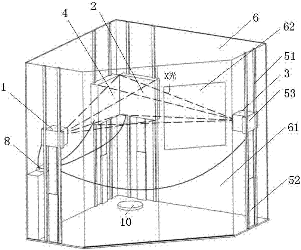
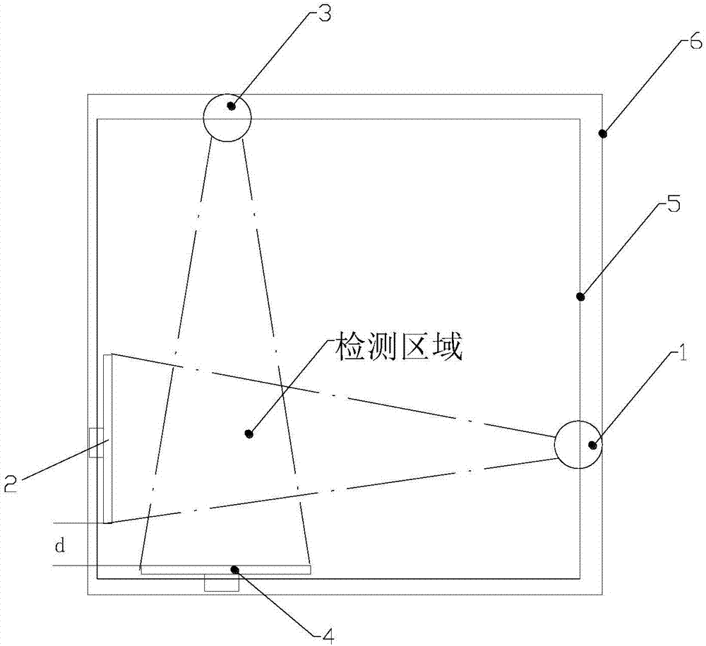
[0062] see figure 1 and figure 2 , the dual X-ray machine system for dynamic fluoroscopy and static use in this embodiment includes: a first X-ray source 1, a first X-ray surface receiver 2, a second X-ray source 3, a second X-ray surface receiver 4, and a synchronous distribution...


PUM


Abstract

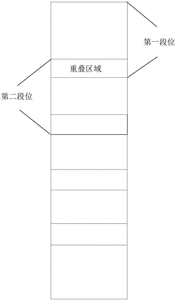
The invention provides a dual-X-ray machine system for dynamic perspective static application and a control method thereof. A synchronous sectioned lifting mechanism is controlled to perform periodic movement and positioning, a dual-X-ray machine is driven to perform synchronous movement for a certain distance in each period, and the periods are positioned in a plurality of sections different in height. Periodic trigger signals are generated through control to trigger a first X-ray light source and a second X-ray light source to only emit one frame of X-ray light in each period to only obtain one frame of surface images on the whole plate surfaces of receiving plates of a first X-ray light surface receiver and a second X-ray light surface receiver in each period, the periods of the trigger signals are same as the movement and positioning periods of the synchronous sectioned lifting mechanism, corresponding trigger signals produce pulses when the synchronous sectioned lifting mechanism is positioned in each section, and accordingly pre-detected part surface images corresponding to all the sections of a first X-ray light surface and a second X-ray light surface are obtained in the whole process. The radiation dosage is greatly decreased by adopting dynamic perspective static application and interrupted transmission of X-ray shot images.

Description

technical field [0001] The invention relates to the field of medical perspective scanning, in particular to a dual X-ray machine system for dynamic perspective and static use and a control method thereof. Background technique [0002] In the current medical technology, the way of scanning the human body to form a fluoroscopic film includes CT scanning and X-ray scanning. Existing X-ray machine systems can only scan a part of the human body from one direction, and only a single-sided partial perspective view is formed, which has great limitations for medical analysis. Moreover, the scanning mode of the existing X-ray machine system is line scanning, which is aimed at the part of the human body and continuously scans from top to bottom, thereby obtaining a complete partial perspective view. Because X-rays have strong radiation, too much radiation will affect the human body. There is great harm to the human body, and the line scanning method needs to emit X-rays from the begin...

Claims


Application Information

Patent Timeline
Patent Type & Authority Patents(China)
IPC IPC(8): A61B6/00A61B6/10
CPCA61B6/00A61B6/107A61B6/4007A61B6/44A61B6/54
Inventor 李国安王少白
Owner SHANGHAI TAOIMAGE MEDICAL TECH CO LTD
Learn More