Transfusion pipeline

A technology for infusion tubes and infusion containers, applied in the field of medical devices, which can solve problems such as contamination of liquid medicine, easy slippage, and hidden medical risks, and achieve the effect of reducing patient costs and saving materials

Pending Publication Date: 2017-01-25
GUANGZHOU JIANZHITANG MEDICAL INSTR CO LTD
View PDF0 Cites 13 Cited by
  • Summary
  • Abstract
  • Description
  • Claims
  • Application Information

AI Technical Summary

Problems solved by technology

[0002] The traditional infusion set has an exposed infusion puncture needle to pierce into the infusion container and discharge the liquid in the container into the infusion set. Nurses need to hold the exposed infusion puncture needle to operate when changing the infusion, which is easy to accidentally injure
[0003] Due to the smooth surface and low adhesion of the infusion puncture needle, when it is inserted into the infusion container, if there are too many and heavy accessories on the infusion set and the infusion set, it is easy to slip off, forming a medical hazard; at the same time, because the puncture needle needs to be partially exposed to the outside world In the air, it is easy to be polluted, and when the polluted puncture needle is punctured into the next bottle of infusion, the liquid medicine will be polluted
[0004] Nurses need to look up to observe the situation of the infusion container when inspecting the infusion situation, and also need to look up to observe the situation of the dripping funnel, which increases the workload of the nurses

Method used


Image

  • Transfusion pipeline
  • Transfusion pipeline
  • Transfusion pipeline

Examples


Embodiment Construction

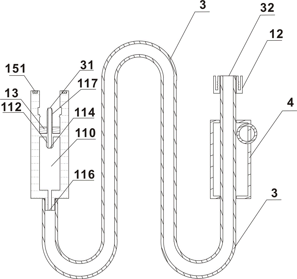
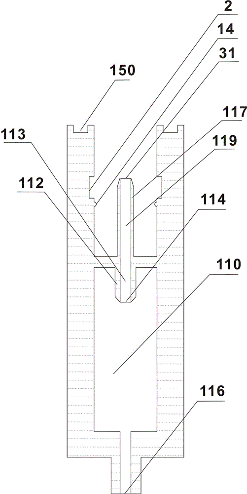
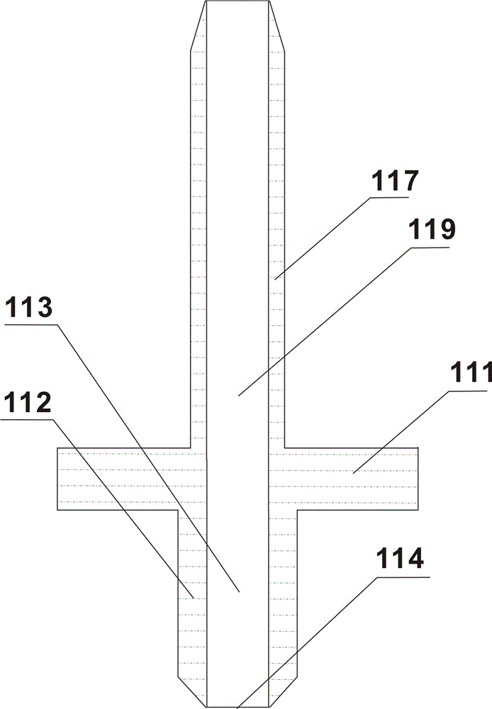
[0081] refer to Figure 1 to Figure 8 , an infusion pipeline, including an infusion catheter 3 provided with an upper infusion connector 11 and a lower infusion connector 12; the upper infusion connector 11 is provided with a hollow cavity 110 and a droplet suspended in the hollow cavity 110 device 111; the upper infusion connector 11 is also provided with an infusion pipeline liquid inlet 31 connected to the discharge port of the peripheral infusion container; ; The dropper 112 is provided with a dropper outlet 114, and the dropper outlet 114 communicates with the infusion pipeline inlet 31; the infusion pipeline is provided with a flow rate regulator 4.

[0082] As a preferred embodiment of the present invention, the infusion conduit 3 adopts an infusion hose.

[0083] As a preferred embodiment of the present invention, at least one section of the infusion hose is provided.

[0084] As a preferred embodiment of the present invention, the external infusion container is an i...


PUM


Abstract

The invention relates to a transfusion pipeline which comprises a transfusion catheter provided with an upper transfusion connector and a lower transfusion connector. The upper transfusion connector is provided with a hollow cavity and a liquid dropping device suspended in the hollow cavity, the upper transfusion connector is further provided with a transfusion pipeline liquid inlet communicated with a peripheral transfusion container liquid outlet, the liquid dropping device is provided with a transfusion puncture device and a liquid dropping tube with a hollow pipeline, the liquid dropping tube is provided with a liquid dropping tube liquid dropping port, and the liquid dropping tube liquid dropping port is communicated with the transfusion pipeline liquid inlet. The transfusion pipeline is provided with a flow velocity regulator. According to the transfusion pipeline, by arranging the transfusion connectors with the outer surfaces provided with inactive structures, the upper transfusion connector is provided with the hollow cavity; only by simply adding the liquid dropping device, the transfusion pipeline can serve as a drip chamber to be applied, materials are saved, and patients' costs are reduced. The transfusion puncture device is arranged in the upper transfusion connector, the uppermost edge of the transfusion puncture device is not protruded out of the upper plane of the upper transfusion connector, and nurses are prevented from being exposed to a sharp puncture device environment during transfusion operation.

Description

technical field [0001] The invention relates to the field of medical devices, in particular to a transfusion pipeline. Background technique [0002] Traditional infusion sets are equipped with exposed infusion puncture needles to pierce into the infusion container and discharge the liquid in the container into the infusion set. Nurses need to hold the exposed infusion puncture needles to operate when changing the infusion, which is easy to accidentally injure. [0003] Due to the smooth surface and low adhesion of the infusion puncture needle, when it is inserted into the infusion container, if there are too many and heavy accessories on the infusion set and the infusion set, it is easy to slip off, forming a medical hazard; at the same time, because the puncture needle needs to be partially exposed to the outside world In the air, it is easy to be polluted, and when the polluted puncture needle is punctured into the next bottle of infusion, the liquid medicine will be pollu...

Claims


Application Information

Patent Timeline
Patent Type & Authority Applications(China)
IPC IPC(8): A61M5/14
CPCA61M5/14A61M2205/75
Inventor 胡绍勤
Owner GUANGZHOU JIANZHITANG MEDICAL INSTR CO LTD
Why Eureka
Try Eureka