Ore cutting device with dust removal function

A cutting device and ore technology, applied in the direction of manufacturing tools, stone processing equipment, work accessories, etc., can solve the problems of affecting the working environment of workers, slow production efficiency, and high production costs, and improve the working environment, accuracy, and operation. handy effect

Inactive Publication Date: 2017-01-25
GUANGZHOU DANJUE COMM TECH CO LTD
0 Cites 18 Cited by

AI-Extracted Technical Summary

Problems solved by technology

The bridge-type stone cutter is most commonly used in stone cutting operations. The side beam ram of the bridge-type stone cutter is movable on the side beam track. The existing side beam track is usually welded and fixed. Due to the large span of the side beam , so long-distance welding is prone to deviation and deformation, which affects the cutting effect of the bridge stone cutter, and the existing side beam track is fixed by welding, its...

Abstract

The invention discloses an ore cutting device with dust removal function, which comprises a dust collecting device and a cutting table, a baffle plate and a fixed base are installed above the cutting table, and a dust suction pipe is arranged on the left side of the baffle plate. A blower is arranged on the right side of the baffle, a crossbeam is installed above the fixed base, a mobile frame is installed above the crossbeam, an electric telescopic rod is connected below the mobile frame, and an electric telescopic rod is connected below the electric telescopic rod. A rotating block is installed, a cutting device is installed under the rotating block, a cutting knife is installed inside the cutting device, a supporting plate is installed under the cutting device, and a shock absorbing device is passed between the cutting table and the base connection, a control box is installed above the base, a motor unit is installed inside the control box, a support frame is installed above the control box, and a stone is placed on the right side of the support frame. The invention has the advantages of simple structure, reasonable design and simple operation, and is worth popularizing.

Application Domain

Technology Topic

Image

  • Ore cutting device with dust removal function

Examples

  • Experimental program(1)

Example Embodiment

[0014] The following will clearly and completely describe the technical solutions in the embodiments of the present invention with reference to the accompanying drawings in the embodiments of the present invention. Obviously, the described embodiments are only some, not all, embodiments of the present invention. Based on the embodiments of the present invention, all other embodiments obtained by persons of ordinary skill in the art without making creative efforts belong to the protection scope of the present invention.
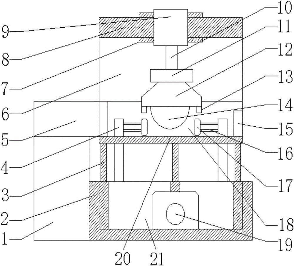
[0015] The present invention provides such figure 1 The shown a kind of ore cutting device with dust removal function includes a dust collecting device 1 and a cutting table 20, a baffle plate 18 and a fixed base 6 are installed above the cutting table 20, and the left side of the baffle plate 18 is provided with Dust suction duct 5, blower 15 is arranged on the right side of described baffle plate 18, crossbeam 8 is installed on the top of described fixed base 6, mobile frame 9 is installed on the top of described crossbeam 8, the below of described mobile frame 9 Connected with an electric telescopic rod 10, a rotary block 11 is installed under the electric telescopic rod 10, a cutting device 12 is installed under the rotary block 11, a cutting knife 14 is installed inside the cutting device 12, and the cutting A supporting plate 13 is installed under the device 12, the cutting table 20 and the base 2 are connected by a shock absorber 3, a control box 21 is installed above the base 2, and a control box 21 is installed inside the control box 21. Motor unit 19, a support frame 4 is installed above the control box 21, and a stone clamp 17 is arranged on the right side of the support frame 4.
[0016] Working principle: The ore cutting device with dust removal function places the ore to be cut on the cutting table 20, and adjusts the distance between two clamping stone blocks 17 by adjusting the length of the connecting rod 16 to determine the clamping ore , to prevent the ore from moving during cutting, resulting in errors. After the ore is clamped by the clamping stone 17, the electric telescopic rod 10 is adjusted to adjust the height of the cutting device 12. After the height is adjusted, the cutting work is performed. Simultaneously, open the blower fan in blower 15 dust-absorbing pipes 5, the dust that cutting produces is collected uniformly; It is used to slow down and buffer the vibration feeling during cutting, and the motor unit 19 is used to provide power.
[0017] Finally, it should be noted that: the above is only a preferred embodiment of the present invention, and is not intended to limit the present invention. Although the present invention has been described in detail with reference to the foregoing embodiments, for those skilled in the art, it still The technical solutions recorded in the foregoing embodiments may be modified, or some of the technical features may be replaced equivalently, and any modifications, equivalent replacements, improvements, etc. made within the spirit and principles of the present invention shall be included in the within the protection scope of the present invention.

PUM

no PUM

Description & Claims & Application Information

We can also present the details of the Description, Claims and Application information to help users get a comprehensive understanding of the technical details of the patent, such as background art, summary of invention, brief description of drawings, description of embodiments, and other original content. On the other hand, users can also determine the specific scope of protection of the technology through the list of claims; as well as understand the changes in the life cycle of the technology with the presentation of the patent timeline. Login to view more.

Similar technology patents

Automatic sludge conveying device for pressure filter

Owner:苏州南风优联环保工程有限公司

Coal-rock drift quick tunnelling method

ActiveCN101975066ASuppression of spontaneous angerImprove working environmentTunnelsDrill holeCoal
Owner:河南省煤层气开发利用有限公司

Classification and recommendation of technical efficacy words

  • Improve working environment
  • Reduce vibration

Pig manure centralized treatment and resource utilization method

Owner:SHANGHAI RUIDAO ENERGY SAVING ENVIRONMENTAL PROTECTION SCI & TECH CO LTD
Why Eureka
Try Eureka