Coolant circulation system for turbocharger

A turbocharger and circulation system technology, applied in the direction of engine cooling, coolant flow control, power unit cooling combination arrangement, etc.

Active Publication Date: 2017-01-25
HYUNDAI MOTOR CO LTD +1
View PDF4 Cites 4 Cited by
  • Summary
  • Abstract
  • Description
  • Claims
  • Application Information

AI Technical Summary

Problems solved by technology

[0007] However, this conventional technique has problems in terms of production

Method used


Image

  • Coolant circulation system for turbocharger
  • Coolant circulation system for turbocharger

Examples


Embodiment Construction

[0022] The following description is merely exemplary in nature and is not intended to limit the invention, application or uses. It should be understood that throughout the drawings, corresponding reference numerals indicate like or corresponding parts and features.

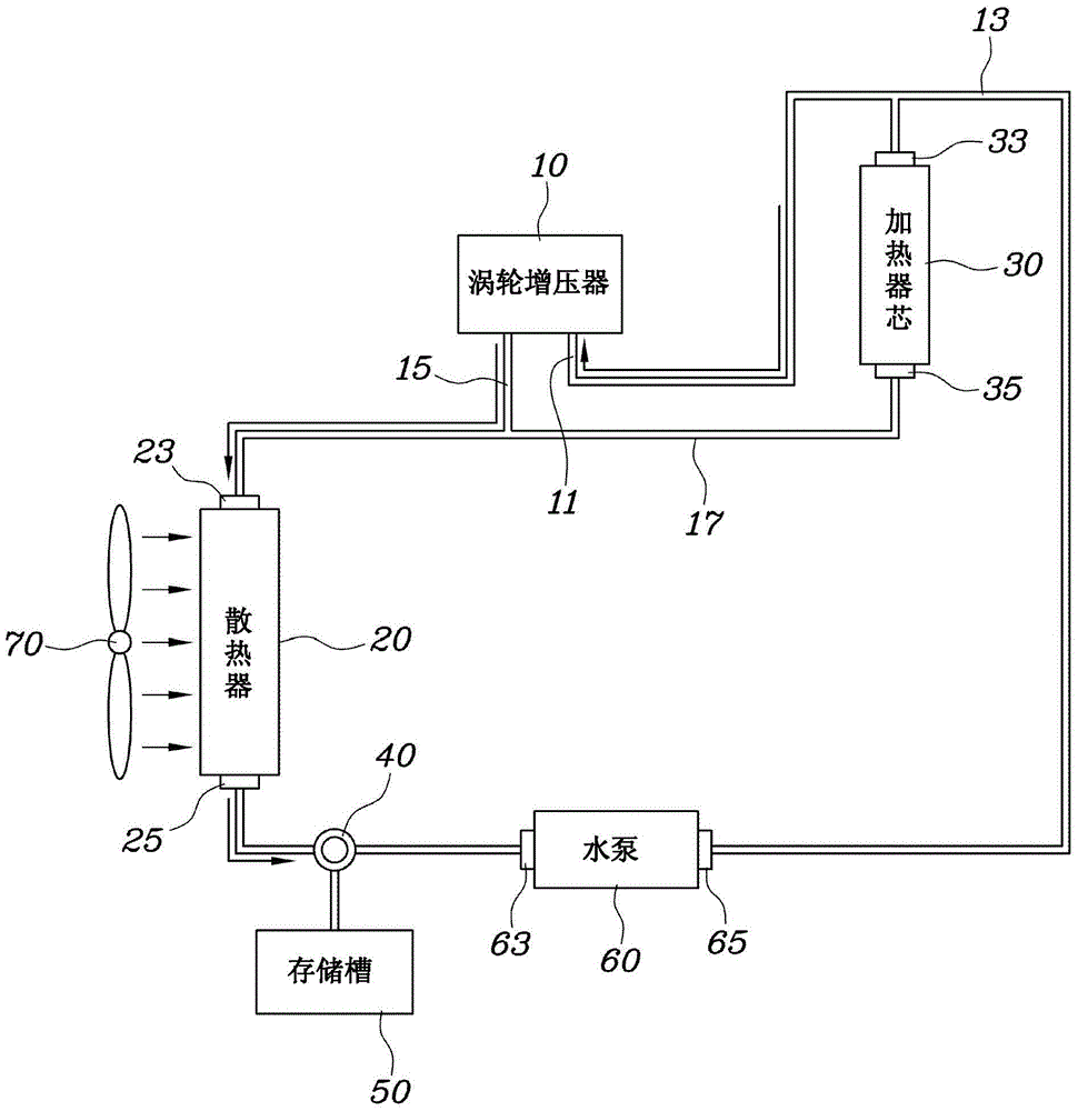
[0023] figure 2 A coolant circulation system for a turbocharger according to an exemplary embodiment of the present invention is explained. refer to figure 2 , the coolant circulation system includes a turbocharger 10 provided with a coolant outlet line 15 and a coolant inlet line 11 . The coolant outlet line 15 through which the coolant exits the turbocharger 10 is connected to a first flow path 17 which connects the inlet end 23 of the radiator to the outlet end 35 of the heater core. A coolant inlet line 11 through which coolant is supplied to the turbocharger 10 is connected to a second flow path 13 which connects the first end 65 of the water pump to the inlet end 33 of the heater core.
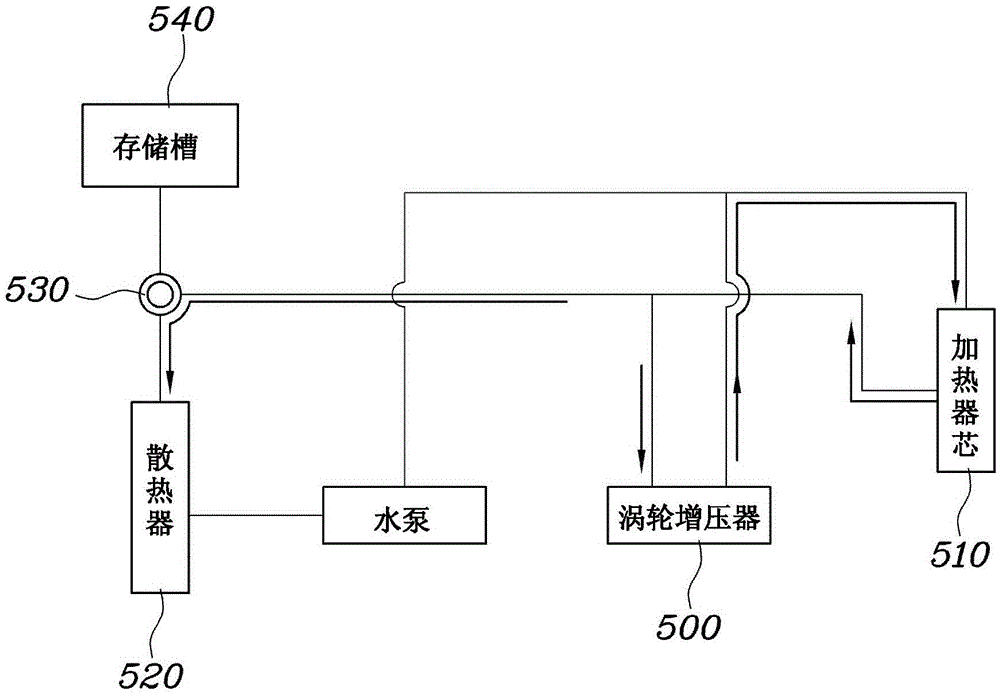
[0024] In conv...


PUM


Abstract

A coolant circulation system for turbochargers is provided. The coolant circulation system includes a turbocharger provided with a coolant outlet line and a coolant inlet line. The coolant is discharged from the turbocharger through the coolant outlet line. The coolant outlet line is connected to a first flow path connecting an inlet port of a radiator to an outlet port of a heater core. The coolant is supplied into the turbocharger through the coolant inlet line. The coolant inlet line is connected to a second flow path connecting a first end of a water pump to an inlet port of the heater core.

Description

technical field [0001] The present invention relates to a coolant circulation system for a turbocharger, which can reduce noise generated by coolant discharged from the turbocharger. Background technique [0002] The statements in this section merely provide background information related to the present invention and may not constitute prior art. [0003] When the engine of the vehicle is stopped after the vehicle is driven, the coolant in the turbocharger is evaporated and discharged therefrom, and thus the turbocharger is maintained in a high temperature state. [0004] figure 1 is a block diagram showing a coolant circulation system for a turbocharger according to conventional technology. When the ignition of the vehicle is turned off while the turbocharger 500 is in a high-temperature state, the coolant is continuously drawn into the turbocharger 500 in a high-temperature state, so that a large amount of steam generated by the coolant boiling phenomenon is transferred ...

Claims


Application Information

Patent Timeline
IPC IPC(8): F02B39/00
CPCF02B39/005F01P3/20F01P2060/12F01P2060/18B60K11/02F01P3/12F01P5/10F01P5/02F01P1/06F01P7/02B60Y2400/435
Inventor 权春奎宋俊昊金南臣丁治源卢炅德李昶远张起龙睦升昊姜声宇
Owner HYUNDAI MOTOR CO LTD
Why Eureka
Try Eureka