Self-cutting undercut anchor

A bottom anchor, self-cutting technology, applied in the direction of connecting components, pins, mechanical equipment, etc., can solve problems such as large impact energy

Active Publication Date: 2017-01-25
FISCHERWERKE ARTUR FISCHER GMBH & CO KG
View PDF9 Cites 6 Cited by
  • Summary
  • Abstract
  • Description
  • Claims
  • Application Information

AI Technical Summary

Problems solved by technology

A disadvantage of the known undercut anchors is that a high impact energy is required to expand the expansion sleeve

Method used


Image

  • Self-cutting undercut anchor
  • Self-cutting undercut anchor
  • Self-cutting undercut anchor

Examples


Embodiment Construction

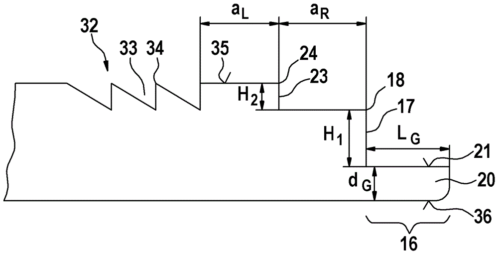
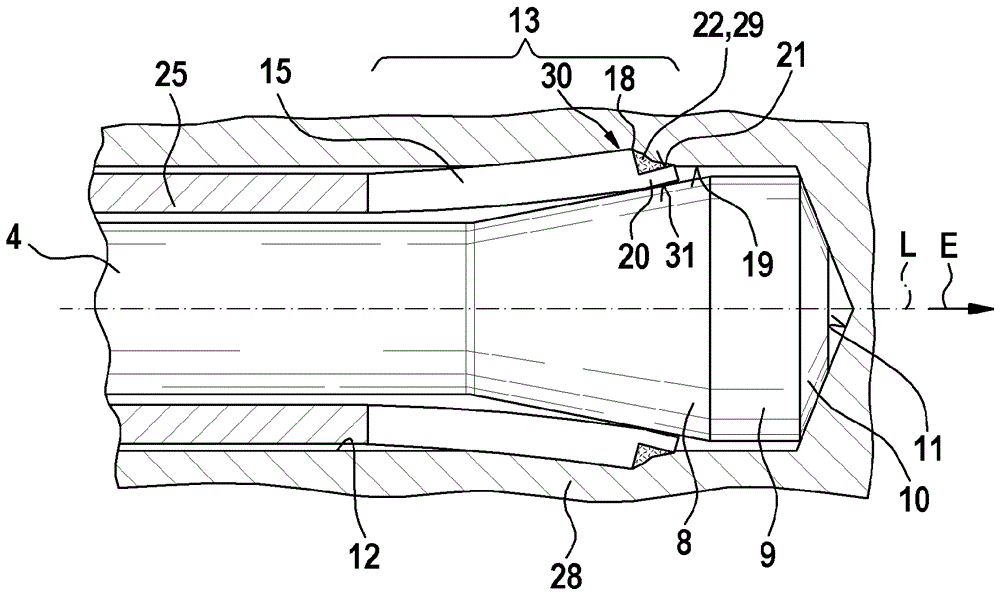
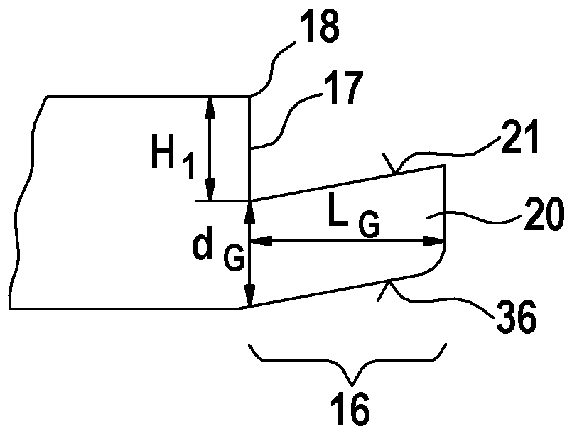
[0029] exist Figures 1 to 3a shows a first undercut anchor 1 according to the invention having an anchor 2 and an inflation sleeve 3 . The anchor 2 is made of steel and comprises an elongated cylindrical body 4 which extends along a longitudinal axis L which runs centrally in the body 4 and also forms the undercut anchor 1 and the expansion sleeve The longitudinal axis L of the barrel 3 . At the rear part of the body 4 in the insertion direction E, an external thread 5 is arranged as a load application device 6 which extends from the rear end of the anchor 2 in the insertion direction E through approximately the anchor 2 / 3 of the length of 2 and can be fastened at a mounting part (not shown) by means of nuts (also not shown). Along the insertion direction E, a swelling body 7 is formed on the anchor 2 . The inflation body 7 has a frusto-conical, conical inflation surface 8 which expands conically in diameter along the insertion direction E. FIG. Along the insertion direct...


PUM


Abstract

The invention relates to a self-cutting undercut anchor (1) provided with an anchor (2) and an expansion sleeve (3). The undercut anchor is anchored in a hole (12) by the expansion of the expansion sleeve (3). By adopting the configuration of the undercut anchor (1), in order to realize the expansion, a setting tool is disposed on the rear end (27) of the expansion sleeve (3) in an inputting direction (E),and the expansion sleeve (3) is pushed to an expansion body (7) by impact, and then a slotted expansion section (13) can be expanded. In order to improve the expansion characteristic of the undercut anchor (1), suggestion is that, the expansion sleeve (3) is provided with a sliding section (16), which is provided with a sliding element (20), and has a diameter gradually reduced, on the front end in the inputting direction (E). At least a first ring level (17) is disposed between the sliding section (16) and the part (25) of the unprotected rear part of the expansion sleeve (3), and the ring level is provided with a first edge (18) embedded in the hole wall of the hole.

Description

technical field [0001] The invention relates to a self-cutting undercut anchor having the features according to the invention. Background technique [0002] Undercut anchors have been known for a long time, with which components can be fastened to the anchor base. Undercut anchors are used, for example, to fasten steel frames to concrete walls or roofs. For this, the undercut anchor is inserted into the eyelet, which is created in the anchor base. The eyelet can already have an undercut before the undercut anchor is introduced, as is known, for example, from laid-open document DE 36 34 431 A1. "Backcut" means the area extending in diameter relative to the remaining area of ​​the generally cylindrical eyelet, which area is formed in the eyelet wall (in most cases in the vicinity of the eyelet floor) and in the After swelling, it engages positively into the undercut anchor. A disadvantage of the undercut anchor known from laid-open document DE 36 34 431 A1 is that a specia...

Claims


Application Information

Patent Timeline
IPC IPC(8): F16B13/06
CPCF16B13/065
Inventor M.林卡D.莱曼
Owner FISCHERWERKE ARTUR FISCHER GMBH & CO KG
Why Eureka
Try Eureka