Automatic valve core component and differential pressure-independent type flow control valve

A technology for flow control valves and automatic valves, applied in the field of balance valves, which can solve the problems of flow control valves without filtering function, complex structure of flow control valves, and increased pipeline system resistance, etc., to achieve compact structure, simple structure, and adjustment and control accuracy high effect

Active Publication Date: 2017-01-25
ZHEJIANG DUNAN INTELLIGENT CONTROL TECH CO LTD
View PDF11 Cites 2 Cited by
  • Summary
  • Abstract
  • Description
  • Claims
  • Application Information

AI Technical Summary

Problems solved by technology

[0003] (1) The pressure guide port behind the flow control valve mentioned above is at the outlet end of the valve body, and it is a pressure guide hole. When the pressure difference between the front and back of the product fluctuates, the pressure transmission behind the valve is not obvious, and the response speed is slow, which affects the adjustment accuracy
[0004] (2) The structure of the above-mentioned flow control valve is complex, difficult to manufacture and process, and the resistance of the fluid flowing through the valve body is relatively large; thus increasing the resistance of the entire pipeline system
[0005] (3) The flow control valves mentioned above mostly adopt low-inlet and high-outlet, or high-inlet and low-outlet structures, and the products are large in size and not compact in structure.
[0006] (4) The flow control valve mentioned above does not have the filtering function, and needs to be equipped with a separate filtering device when in use
[0007] (5) The manual adjustment spool of the above-mentioned flow control valve only has the adjustment function, not the shut-off function

Method used


Image

  • Automatic valve core component and differential pressure-independent type flow control valve
  • Automatic valve core component and differential pressure-independent type flow control valve
  • Automatic valve core component and differential pressure-independent type flow control valve

Examples


Embodiment Construction

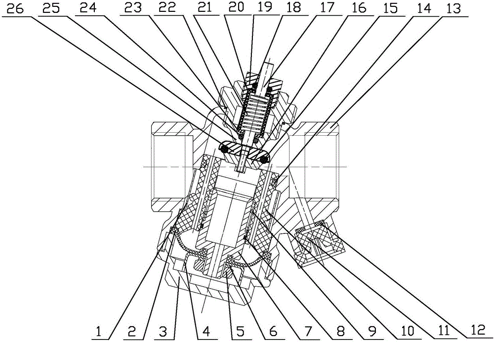
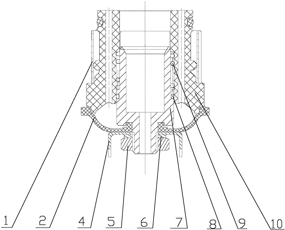
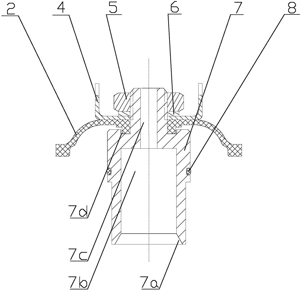
[0043] In this embodiment, a differential pressure independent flow control valve is combined with figure 1 , including an automatic valve core assembly, a lower valve cover 3, a valve body 13, a linear disc 16, a valve stem 17, an upper valve cover 25 and a support plate 26, combined figure 2 , image 3 and Figure 4 , the automatic spool assembly includes a pressure-sensitive diaphragm 2, a pressing disc 4, an adjusting spool 7 and a spool sleeve 10, combined Figure 5 and Figure 6, the valve core sleeve 10 is a cylindrical multi-boss sleeve structure, and its upper end surface is provided with a water guide hole 10b, and the water guide hole 10b directly leads to a stepped hole on its lower end surface, and the stepped hole and the middle part of the valve core sleeve 10 are provided with a rectangular groove communicate with each other to ensure the passage of the upstream medium; the regulating valve core 7 is a stepped cylindrical sleeve structure, and its upper end...


PUM


Abstract

The invention relates to an automatic valve core component and a differential pressure-independent type flow control valve and belongs to the technical field of balance valves. The automatic valve core component comprises a pressure-sensitive diaphragm, a compressing disc, a regulating valve core and a valve core sleeve, wherein the valve core sleeve is of a cylinder multi-boss sleeve structure, a water guiding hole is formed in the upper end face of the valve core sleeve, the regulating valve core is of a cylinder sleeve structure provided with steps, a thin-wall cutting edge is formed in the upper end face of the regulating valve core, a groove is formed in the lower end of the regulating valve core, the groove is matched with an intermediate hole boss of the pressure-sensitive diaphragm, and the groove runs through a center hole of the pressure-sensitive diaphragm to the compressing disc below the pressure-sensitive diaphragm; and the valve core sleeve sheathes on the outer wall of the regulating valve core. The automatic valve core component provided by the invention has the advantages of high regulation precision, small size, no influence on flow and guarantee of independent implementation of regulating and closing functions.

Description

technical field [0001] The invention relates to an automatic valve core assembly and a pressure-difference-independent flow control valve, belonging to the technical field of balance valves. Background technique [0002] In the fluid medium pipeline control system, when the pressure in the pipeline system fluctuates, in order to keep the outlet flow stable, a flow control valve is usually used. Among the known products, the patent No. ZL201110033130.1 discloses a working pressure For a flow control valve with a fixed differential range, the working pressure difference is determined by a fixed and non-adjustable spring; patent ZL201020285505 discloses a variable pressure difference flow control valve that changes the working pressure difference by adjusting the spring with a screw. However, these products generally have the following problems: [0003] (1) The pressure guide port behind the flow control valve mentioned above is at the outlet end of the valve body, and it is ...

Claims


Application Information

Patent Timeline
Patent Type & Authority Applications(China)
IPC IPC(8): F16K17/22F16K3/314F16K31/126F16K3/26F16K13/00F16K1/48B01D35/04
CPCB01D35/04F16K1/48F16K3/267F16K3/314F16K17/22F16K31/126
Inventor 叶琛朱新炎俞冠正
Owner ZHEJIANG DUNAN INTELLIGENT CONTROL TECH CO LTD
Why Eureka
Try Eureka