
Multi-liquid hydrogen storage tank parallel-connection injection method for hydrogen-oxygen rocket tests
A technology for testing and storage tanks, which is applied in container filling methods, container discharge methods, gas/liquid distribution and storage, etc., and can solve problems such as fluctuations in filling flow, different storage volumes, and complex liquid hydrogen filling processes. To achieve the effect of eliminating fluctuation shocks
- Summary
- Abstract
- Description
- Claims
- Application Information
AI Technical Summary
Problems solved by technology
Method used
Image

Examples
Embodiment Construction
[0008] The present invention will be described in detail below in conjunction with the accompanying drawings and specific embodiments.
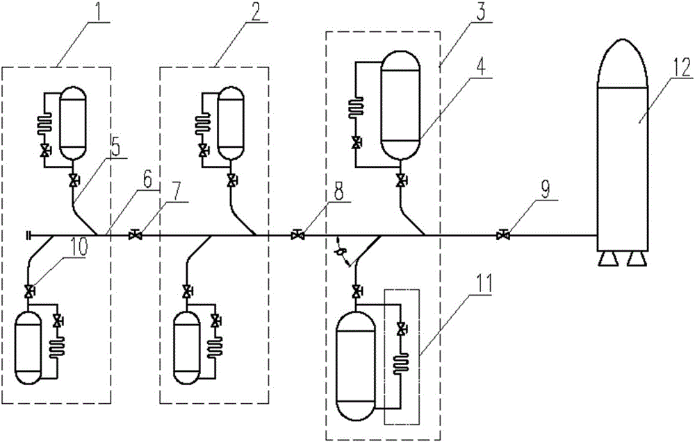
[0009] As shown in the accompanying drawings, the present invention consists of a precooling filling storage tank group 1, a small flow filling storage tank group 2, a large flow filling storage tank group 3, a liquid hydrogen storage tank 4, a branch pipeline 5, a main pipeline 6, It is composed of pre-cooling cut-off valve 7, small flow cut-off valve 8, total liquid outlet valve 9, liquid hydrogen storage tank filling and discharging valve 10, liquid hydrogen storage tank self-pressurization system 11 and other parts. First of all, when designing the branch pipeline and the main pipeline, the angle β between the branch pipeline and the main pipeline is considered, generally 30°~45°, which reduces the impact during the confluence process of the branch pipeline and is conducive to the stability of filling. Furthermore, according to the distan...
PUM
 Abstract
Description
Claims
Application Information