Method for detecting touch positions in infrared touch screen and terminal equipment

An infrared touch screen and touch position technology, applied in the input/output process of data processing, instruments, electrical digital data processing, etc., can solve the problems of touch point coordinate error, difference, and no actual touch, so as to avoid influence and improve accuracy sexual effect

Active Publication Date: 2017-01-25
HISENSE VISUAL TECH CO LTD
View PDF5 Cites 9 Cited by
  • Summary
  • Abstract
  • Description
  • Claims
  • Application Information

AI Technical Summary

Problems solved by technology

[0004] However, when locating the touch occlusion area in each scanning direction, usually due to the shadow or light interference at the edge of the touch point, there will be no actual touch in some areas on both sides of the touch occlusion area in the curre...

Method used


Image

  • Method for detecting touch positions in infrared touch screen and terminal equipment
  • Method for detecting touch positions in infrared touch screen and terminal equipment
  • Method for detecting touch positions in infrared touch screen and terminal equipment

Examples


Embodiment Construction

[0060] Reference will now be made in detail to the exemplary embodiments, examples of which are illustrated in the accompanying drawings. When the following description refers to the accompanying drawings, the same numerals in different drawings refer to the same or similar elements unless otherwise indicated. The implementations described in the following exemplary examples do not represent all implementations consistent with the present invention. Rather, they are merely examples of apparatuses and methods consistent with aspects of the invention as recited in the appended claims.

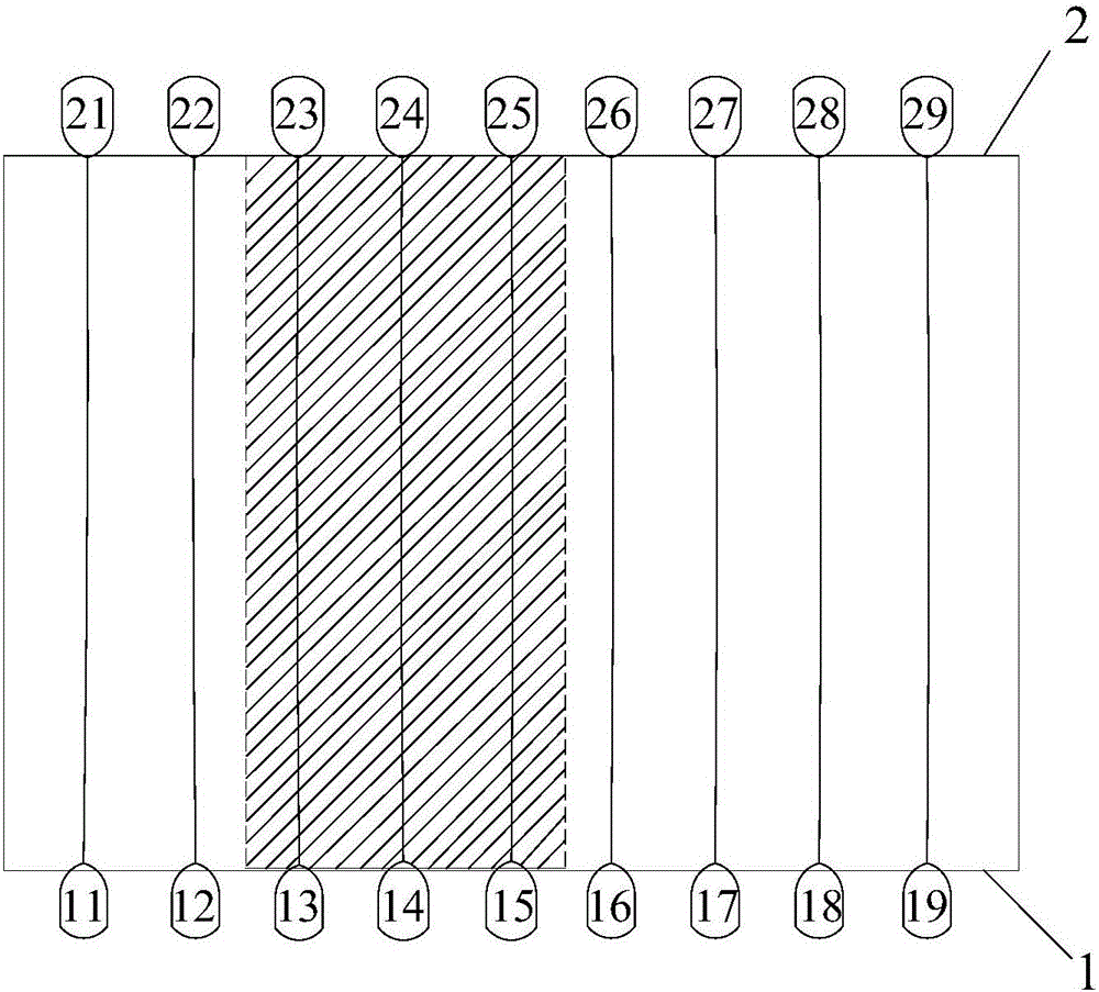
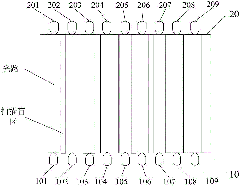
[0061] figure 2 It is a schematic structural diagram of an infrared touch screen shown according to an exemplary embodiment. The method for detecting a touch position in an infrared touch screen provided by an embodiment of the present invention is implemented by taking the infrared touch screen as an example.

[0062] Such as figure 2 As shown, the infrared touch screen includes a touch scr...


PUM


Abstract

The invention relates to a method for detecting touch positions in an infrared touch screen and terminal equipment. The method comprises steps as follows: detecting an analog light intensity value of each light path in a preset scanning direction of the touch screen; determining touch shading areas in the preset scanning direction according to the analog light intensity values of the light paths; correcting boundaries of the touch shading areas according to light path width to obtain corrected touch shading areas; determining the infrared touch positions on the touch screen according to the corrected touch shading areas. According to the embodiment, the boundaries of the touch shading areas are corrected according to the light path width, so that shadows in edge positions of touch points on the scanning light paths can be prevented from affecting or interfering the touch shading areas, the more accurate touch shading areas in the preset scanning direction can be calculated, and the touch positions are accurately determined.

Description

technical field [0001] The invention relates to the field of touch technology, in particular to a method for detecting a touch position in an infrared touch screen and a terminal device. Background technique [0002] Infrared touch screens have been widely used due to the advantages of simple production process, low production cost, convenient installation and high reliability. The basic structure of the infrared touch screen includes the touch screen and a number of infrared emitting lamps and infrared receiving lamps arranged around the touch screen. The infrared light is received by the infrared receiving lamp on the opposite side. When there is a touch operation, the light passing through the touched position will be blocked or weakened. The processor calculates the position where the touch operation occurs based on the blocked or weakened light path. [0003] Such as figure 1 Shown is a rectangular infrared touch screen, the rectangular infrared touch screen includes ...

Claims


Application Information

Patent Timeline
IPC IPC(8): G06F3/042
CPCG06F3/0428
Inventor 王武军马亮曹建伟
Owner HISENSE VISUAL TECH CO LTD
Why Eureka
Try Eureka