Eureka AIR delivers breakthrough ideas for toughest innovation challenges, trusted by R&D personnel around the world.

Light path detecting method and device

A technology of optical path detection and optical path, which is applied to the detection of faulty computer hardware, etc., can solve the problems of invalid optical path misjudgment, wrong judgment, long time, etc., to shorten time-consuming, accurate judgment, and reduce the probability of misjudgment Effect

Active Publication Date: 2017-01-25
HISENSE VISUAL TECH CO LTD
View PDF7 Cites 2 Cited by
  • Summary
  • Abstract
  • Description
  • Claims
  • Application Information

AI Technical Summary

Problems solved by technology

[0009] For method one, the detection process needs to wait for the timeout judgment, which takes a long time
And it is easy to lead to misjudgment. For example, if the same area is pressed for a long time during the movement of the touching object, the duration of the light path of the touch area being blocked may exceed the duration threshold set by Method 1. In this case, there will be a misjudgment of the invalid optical path, which will affect the calculation of the touch point.
[0010] For the second method, it is necessary to judge whether the optical path is valid only when there is no touching object on the screen, and the judgment process takes too long
[0011] As mentioned above, in the prior art, there are defects in the detection schemes for judging whether the optical path is effective

Method used


Image

  • Light path detecting method and device
  • Light path detecting method and device
  • Light path detecting method and device

Examples


Embodiment Construction

[0065] As stated in the background technology of this application, the existing detection scheme requires a long time-consuming detection, whether it is waiting for timeout or receiving algorithm feedback, it requires a long waiting time, which is not conducive to the rapidity requirements of optical path detection, and due to The diversity of touch operations and the high probability of misjudgment in existing detection schemes also affect the accuracy of optical path detection.

[0066] The inventor of the present application hopes to use the method provided in this application to more effectively and accurately detect failures such as broken lamps and broken lines in the touch screen of the current infrared scanning device, and to realize fast and accurate troubleshooting for invalid optical paths in the touch screen. Minimize the time spent on troubleshooting faults such as bad lamps and wires in the touch screen, and on this basis, improve the fault detection speed and sca...


PUM


Abstract

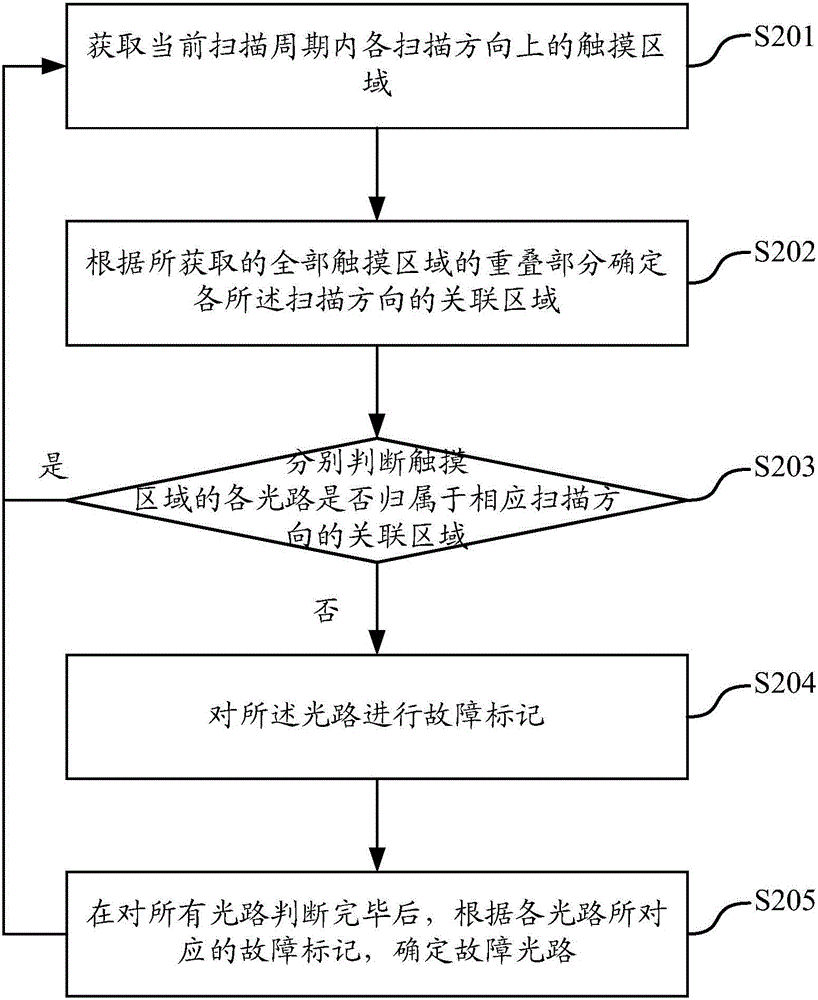
The embodiment of the invention provides a light path detecting method and device. The method includes the steps of determining the related area in the corresponding scanning direction according to the overlapped part of touch areas in all light path scanning directions, and detecting fault light paths according to whether light paths contained in the touch area in one scanning direction belong to the related area of the scanning direction or not. By means of the method, the fault light paths can be directly and rapidly determined according to the result of light path scanning, the time consumption in the detecting process is effectively shortened, the misjudgment probability is reduced, and the aim of rapidly and accurately judging light path faults in an infrared touch screen is achieved.

Description

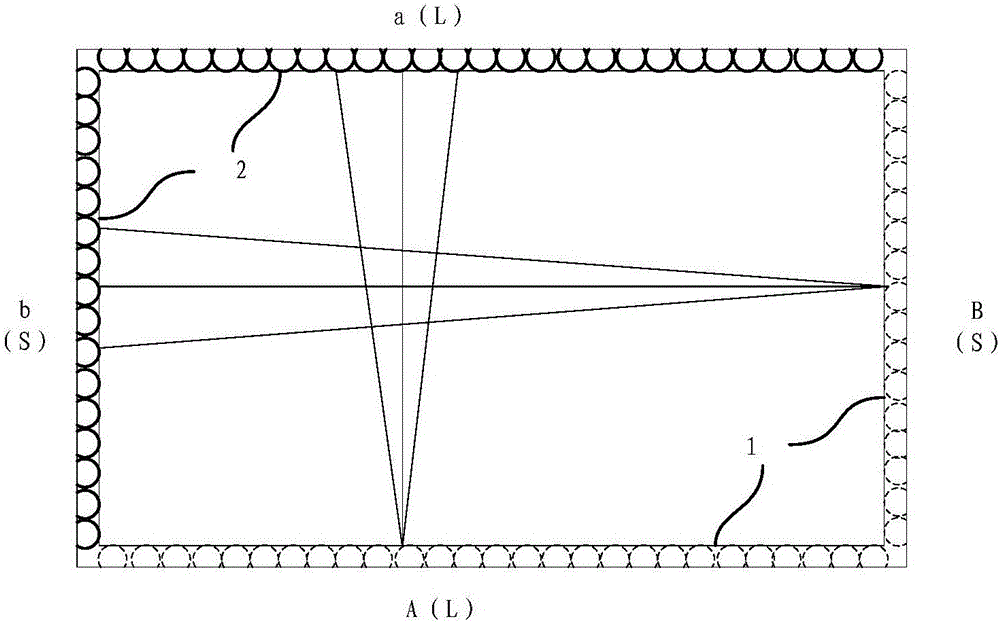
technical field [0001] The present application relates to the field of touch control, in particular to an optical path detection method, and in particular to an optical path detection device. Background technique [0002] Infrared Touch Screen Technology (Infrared Touch Screen Technology) is composed of infrared emitting and receiving sensing elements installed on the outer frame of the touch screen. On the surface of the screen, an infrared detection network is formed. Any touching object can change the infrared rays on the contacts to realize touch screen operation. . It simplifies the human-computer interaction method. In the current touch technology, infrared touch technology has the advantages of strong environmental adaptability, longer life, and more identifiable touch points. [0003] The appearance of the infrared touch screen is a rectangular structure, as shown in the attached figure 1 As shown, it consists of a long transmitting side A(L), a long receiving side...

Claims


Application Information

Patent Timeline
IPC IPC(8): G06F11/22
Inventor 张晓娜马亮薛晓光李新
Owner HISENSE VISUAL TECH CO LTD
Why Eureka
Eureka Blog
Learn More