X-ray bulb tube

An X-ray and ball tube technology, applied in the X-ray field, can solve problems such as fracture of the thin-walled shaft 41, complicated manufacturing process, and reduction of the thickness of the thin-walled shaft 41, so as to achieve the effect of strengthening strength and reducing temperature conduction

Active Publication Date: 2017-01-25
SHANGHAI UNITED IMAGING HEALTHCARE
View PDF6 Cites 3 Cited by
  • Summary
  • Abstract
  • Description
  • Claims
  • Application Information

AI Technical Summary

Problems solved by technology

However, this method of screwing the heat shield 10 on the thin-walled shaft 41 will cause the heat shield 10 to be in surface contact with the rotating part 40, so that the heat on the heat shield 10 is conducted to the rotating part 40 through the thin-walled shaft 41, It affects the life of the rotating part 40. At the same time, in order to install the heat-resistant plate 10 on the thin-walled shaft 41, threads should be provided on the thin-walled shaft 41, which further reduces the thickness of the thin-walled shaft 41 and affects the thin-walled shaft 41. The rigidity of the wall shaft 41 may even cause the thin-wall shaft 41 to break during high-speed rotation
[0005] In some other schemes, in order to strengthen the rigidity of the thin-walled shaft 41, a protruding ring (not shown) is provided on the thin-walled shaft 41, and threads are provided on the protruding ring to screw the heat shield 10 On the protruding ring, but the heat resistance effect of this structure is not ideal (the heat resistance plate is connected to the rotating part), and the manufacturing process is complicated

Method used


Image

  • X-ray bulb tube
  • X-ray bulb tube
  • X-ray bulb tube

Examples


Embodiment 1

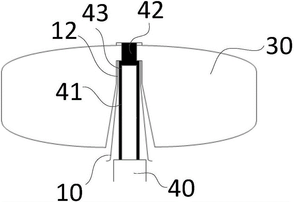
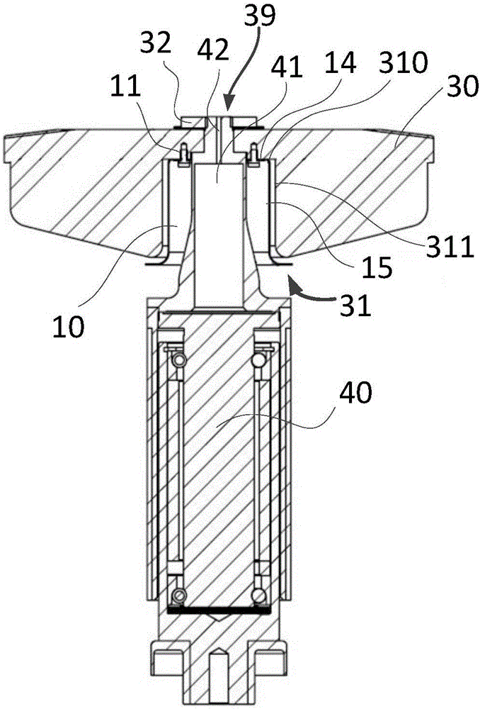
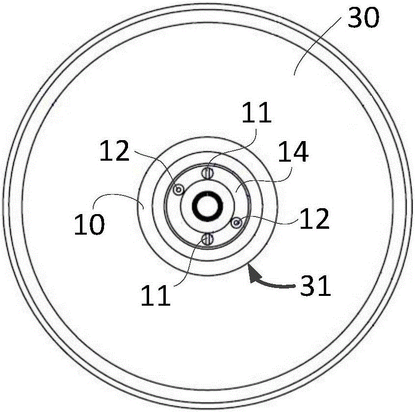
[0027] figure 2 is a schematic vertical sectional view of the target disk according to the first embodiment. Such as figure 2 As shown, the X-ray tube provided in this embodiment includes a target disc and a rotating part that drives the target disc to rotate, wherein the target disc 30 includes a target surface that can generate X-rays under the impact of electrons, and the The target plate 30 is also defined with a positioning groove 31 on its central axis on the opposite side to the target surface, so that when the rotating portion 40 is fixed to the target plate 30, the positioning groove 31 is aligned with the rotating portion 40 An annular space is defined between the circumferential side walls of the rotating part 40 and the target disc 30 is also provided with a heat-resistant plate 10, and the heat-resistant plate 10 is fixed to the target disc 30 within the annular space. superior.

[0028] High-speed electrons impact on the target surface of the target disk 30 ...

Embodiment 2

[0035] Figure 4 is a schematic vertical sectional view of the target disk according to the second embodiment. Such as Figure 4 As shown, the connection mode and shape of the rotating part 40 and the target disk 30 in this embodiment are basically the same as those in Embodiment 1, and will not be repeated here. Different from Embodiment 1, at least two layers of heat-resisting plates 10 are used in this embodiment. Taking the use of two-layers of heat-resisting plates 10 as an example, the heat-resisting plate 10 close to the thin-walled shaft 41 is the inner heat-resisting plate 10a, far away from the thin-walled The heat shield 10 of the shaft 41 is an outer heat shield 10b. The outer heat-resisting plate 10b has a diameter larger than that of the inner heat-resisting plate 10a, and respectively includes a substantially flat fixed portion and a heat-resistant portion extending angularly from the fixed portion.

[0036] Figure 5 is a schematic diagram of the installati...

Embodiment 3

[0043] Figure 6 is a schematic vertical cross-sectional view of a target disk according to a third embodiment. Such as Figure 6 As shown, the X-ray tube according to this embodiment includes a target disc 30 that generates X-rays 60 under the impact of electrons 50, and a rotating part 40 that drives the target disc 30 to rotate. The target disc 30 includes a metal material The first part 35 constituted and the second part 32 constituted by heat capacitive material, the rotating part 40 is connected to the first part 35 of the target disk 30, and a heat shield 10 is arranged between the target disk 30 and the rotating part 40, so The heat shield 10 is fixed on the first portion 35 of the target disk 30 .

[0044] On the upper surface of the first part 35, on the position of electron bombardment, a high-temperature heat-resistant layer 34 is provided. The high-temperature heat-resistant layer 34 is the position directly bombarded by electrons, and the temperature is the hig...


PUM


Abstract

The invention relates to an X-ray bulb tube. The X-ray bulb tube comprises a target disc and a rotating part used or driving the target disc to rotate, wherein the target disc comprises a target surface which can produce X rays under impact of electrons, and a locating slot is also limited at central axis of the target disc at a side opposite to the target surface, so that an annular gap is defined between the locating slot and the circumferential side wall of the rotating part when the rotating part is fixedly arranged on the target disc, a heat-resistant plate is also arranged between the rotating part and the target disc, and the heat-resistant plate is fixedly arranged on the target disc in the annular gap. According to the invention, the heat-resistant plate of the X-ray bulb tube is fixedly arranged on the target disc and is not in surface contact with the rotating part, so that strength of the rotating part can be strengthened, and conduction of temperature of a reflecting piece onto a fixed shaft is also effectively reduced.

Description

technical field [0001] The invention relates to the field of X-rays, in particular to an X-ray tube for generating X-rays. Background technique [0002] X-ray tube (X-ray tube) can generate X-rays used to generate fluoroscopic images. In the process of generating X-rays, such as CT (Computed Tomography) imaging equipment, high-speed electrons in the X-ray tube bombard the target On the disk, the temperature of the target disk rises. In order to avoid the damage of the target disk due to the temperature rise, the general method is to use the motor to drive the target disk to rotate at a high speed (the speed can reach 6000 rpm), so that the target disk is evenly heated. , to avoid cracking of the target disc. [0003] Because the high temperature of the target disk will be conducted and radiated to the rotor of the motor and the bearing fixed to the rotor, and the high-speed rotating friction of the bearing fixed to the rotor of the motor will also increase the temperature o...

Claims


Application Information

Patent Timeline
Patent Type & Authority Applications(China)
IPC IPC(8): H01J35/10H01J35/26
CPCH01J35/101H01J35/26H01J2235/1046H01J2235/1208
Inventor 张云华张曦
Owner SHANGHAI UNITED IMAGING HEALTHCARE
Why Eureka
Try Eureka