Device and method for processing connector of superconducting wire contact
A superconducting wire and joint connection technology, applied in the direction of connection, circuit/collector parts, electrical components, etc., can solve the problems of superconducting layer damage, wavy appearance, loss of superconducting current transmission capacity, etc. Good superconducting performance, low cost, good effect of transmitting large current
- Summary
- Abstract
- Description
- Claims
- Application Information
AI Technical Summary
Problems solved by technology
Method used
Image
Examples
Embodiment 1
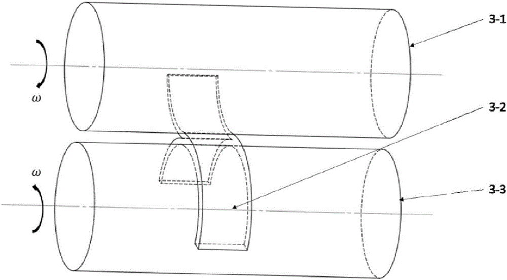
[0061] This example will combine Figure 1 to Figure 4 To describe, the structure of the second-generation high-temperature superconducting wire can be used figure 1 to indicate, including: upper strengthening layer 1-1, silver stabilization layer 1-2, superconducting layer 1-3, transition layer 1-4, metal substrate 1-5, lower strengthening layer 1-6, the dotted line box is about Sites 1-7 for directly separating the superconducting layer from the transition layer. figure 2 The middle indicates the superconducting layer and the transition layer port that have been directly separated. Splitting process such as image 3 , Figure 4 as shown, image 3 It includes an upper roller 3-1; a superconducting wire 3-2 for splitting; a lower roller 3-3. Figure 4 yes image 3 , where 4-4 represents the split superconducting layer; 4-5 represents the split transition layer.
[0062] A processing method for a superconducting wire joint connection body includes the following steps: ...
Embodiment 2
[0079] This embodiment combines figure 1 , figure 2 , Figure 5 , Figure 6 To describe, a processing and application technology of a superconducting wire joint connection body includes the following steps:
[0080] S1) Prepare a second-generation high-temperature superconducting wire joint connector processing equipment as claimed in claim 1, and intercept a second-generation high-temperature superconducting wire with a length of 10-100 mm and a width of 4-12 mm;
[0081] S2) At one end of the superconducting wire, separate the wire by a length of 1-5mm along the interface between the transition layer and the superconducting layer;
[0082] S3) fixing the side where the metal base of the wire is on the surface of the flat plate, and fixing the other side where the superconducting layer of the wire is on the surface of the roller;
[0083] S4) Adjust the distance between the rollers and the flat plate to be the same as the thickness of the conductors, and rotate the two rol...
Embodiment 3
[0089] This embodiment combines Figure 7 describe, Figure 7 The structure of the superconducting wire used in this embodiment is shown, including: upper strengthening layer 7-1; silver stabilizing layer 7-2; superconducting layer 7-3; transition layer 7-4; metal substrate 7-5; Silver layer 7-6; lower reinforcement layer 7-7. Sites 7-8 for tearing small openings.
[0090] The processing and application of a superconducting wire joint connection body, the steps comprising:
[0091] S1) Prepare a second-generation high-temperature superconducting wire joint connection body processing equipment, and intercept a second-generation high-temperature superconducting wire with a length of 10-100 mm and a width of 4-12 mm;
[0092] S2) Use tweezers or other tools to separate the silver layer close to the lower surface from the metal base, and separate completely, and only keep the part containing the metal base as the material for subsequent processing;
[0093] S3) At one end of t...
PUM
| Property | Measurement | Unit |
|---|---|---|
| Radius | aaaaa | aaaaa |
Abstract
Description
Claims
Application Information
 - R&D
- Intellectual Property
- Life Sciences
- Materials
- Tech Scout
- Unparalleled Data Quality
- Higher Quality Content
- 60% Fewer Hallucinations
Browse by: Latest US Patents, China's latest patents, Technical Efficacy Thesaurus, Application Domain, Technology Topic, Popular Technical Reports.
© 2025 PatSnap. All rights reserved.Legal|Privacy policy|Modern Slavery Act Transparency Statement|Sitemap|About US| Contact US: help@patsnap.com


