Supercharge Your Innovation With Domain-Expert AI Agents!

A motor rotor, a motor using the motor rotor, and a calculation method for the angle of the motor rotor

A technology of motor rotor and calculation method, applied in the electrical field, can solve problems such as high cost and troublesome production, and achieve the effect of reducing back electromotive force harmonics and improving motor performance

Active Publication Date: 2019-05-31
SHENZHEN HOBBYWING TECH CO LTD
View PDF6 Cites 0 Cited by
  • Summary
  • Abstract
  • Description
  • Claims
  • Application Information

AI Technical Summary

Problems solved by technology

[0002] The motor rotor used in the motor now requires the preparation of rotor segments of different lengths for motors of the same series with different powers, which is troublesome to produce; in addition, in order to reduce the back electromotive force harmonics of the motor, the rotor segment needs to be made with oblique poles, or the stator should be made Into a chute, the cost is relatively high

Method used


Image

  • A motor rotor, a motor using the motor rotor, and a calculation method for the angle of the motor rotor
  • A motor rotor, a motor using the motor rotor, and a calculation method for the angle of the motor rotor
  • A motor rotor, a motor using the motor rotor, and a calculation method for the angle of the motor rotor

Examples


Embodiment Construction

[0024] In order to make the method of the present invention clearer and clearer, it will be described in further detail below in conjunction with specific embodiments and accompanying drawings:

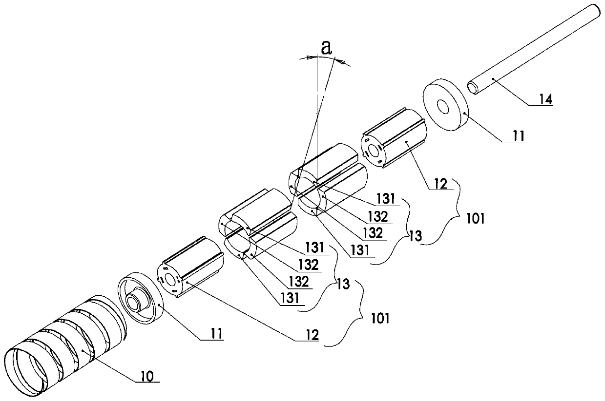
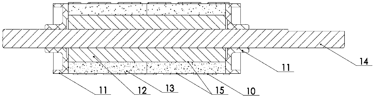
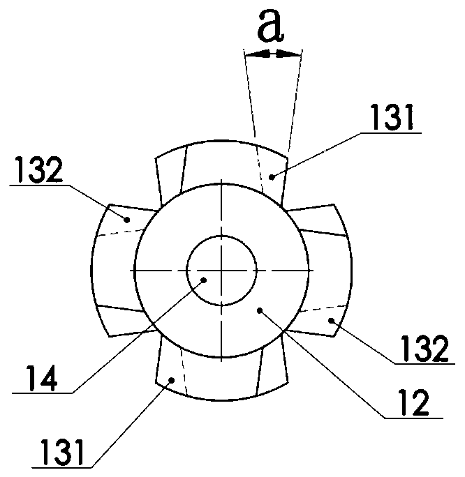
[0025] Embodiment No. 1 of the present invention, such as figure 1 , figure 2 , image 3 Shown:

[0026] The motor rotor 1 includes a shaft 14 , fibers 10 , glue 15 , two rotor segments 101 , and two dynamic balance correction plates 11 .

[0027] Each rotor segment 101 is quasi-cylindrical and includes four sector magnets 131 and 132 and an iron core 12 .

[0028] Among the magnets 131 and 132, there are 2 pieces of N pole magnets 131 with the N poles facing the outer surface, and 2 pieces of S pole magnets 132 with the S poles facing the outer surface. The N pole magnets 131 and the S pole magnets 132 are alternately arranged in a symmetrical manner distributed.

[0029] The iron core 12 is a quasi-cylindrical body with a hole in the middle; between the shaft 14 and the magnet...


PUM


Abstract

The invention relates to the electrical field, in particular to a motor rotor used in a motor, a motor applying the motor rotor and a method for calculating an angle of the motor rotor. The motor rotor is provided with a shaft in the middle, the shaft passes through more than two rotor sections, and the rotor sections are mutually staggered for a certain angle; the angle is calculated according to an equation that a is less than or equal to 360 / [s,4] / n; the brushless motor also comprises an end cover and a stator; the motor applying the motor rotor can be matched with different quantities of rotor sections, and series motors with different powers are expanded; meanwhile, the rotor sections are mutually staggered for a certain angle, counter electromotive force harmonic of the motor is lower, and performance of the motor is improved.

Description

technical field [0001] The invention relates to the electrical field, in particular to a motor rotor used in a motor and the motor. Background technique [0002] The motor rotors used in motors now need to prepare rotor segments of different lengths for motors of the same series with different powers, which is troublesome to produce; in addition, in order to reduce the back electromotive force harmonics of the motor, the rotor segments need to be made with oblique poles, or the stator should be made Into a chute, the cost is relatively high. Contents of the invention [0003] The main purpose of the present invention is to improve the existing technology, use rotor segments of different lengths to spell out motors of the same series with different powers; in addition, each rotor segment is staggered by a certain angle, which reduces the back electromotive force harmonics of the motor and improves the performance of the motor Effect. [0004] Preferably, the motor rotor i...

Claims


Application Information

Patent Timeline
Patent Type & Authority Patents(China)
IPC IPC(8): H02K1/27H02K7/04H02K11/21H02K21/14
CPCH02K1/27H02K1/2753H02K7/04H02K21/14H02K2213/03
Inventor 唐雷
Owner SHENZHEN HOBBYWING TECH CO LTD
Features
  • R&D
  • Intellectual Property
  • Life Sciences
  • Materials
  • Tech Scout
  • Unparalleled Data Quality
  • Higher Quality Content
  • 60% Fewer Hallucinations
Learn More