Metal shell of communication equipment and preparation method thereof
A technology for metal casings and communication equipment, applied in the directions of metal casings, slot antennas, telephone structures, etc., can solve the problems of damage to the overall structure of the metal mobile phone body, affecting the overall cleanliness and continuity of the appearance, and achieve improved hardness, appearance, etc. View neat, smooth and consistent effect
- Summary
- Abstract
- Description
- Claims
- Application Information
AI Technical Summary
Problems solved by technology
Method used
Image
Examples
preparation example Construction
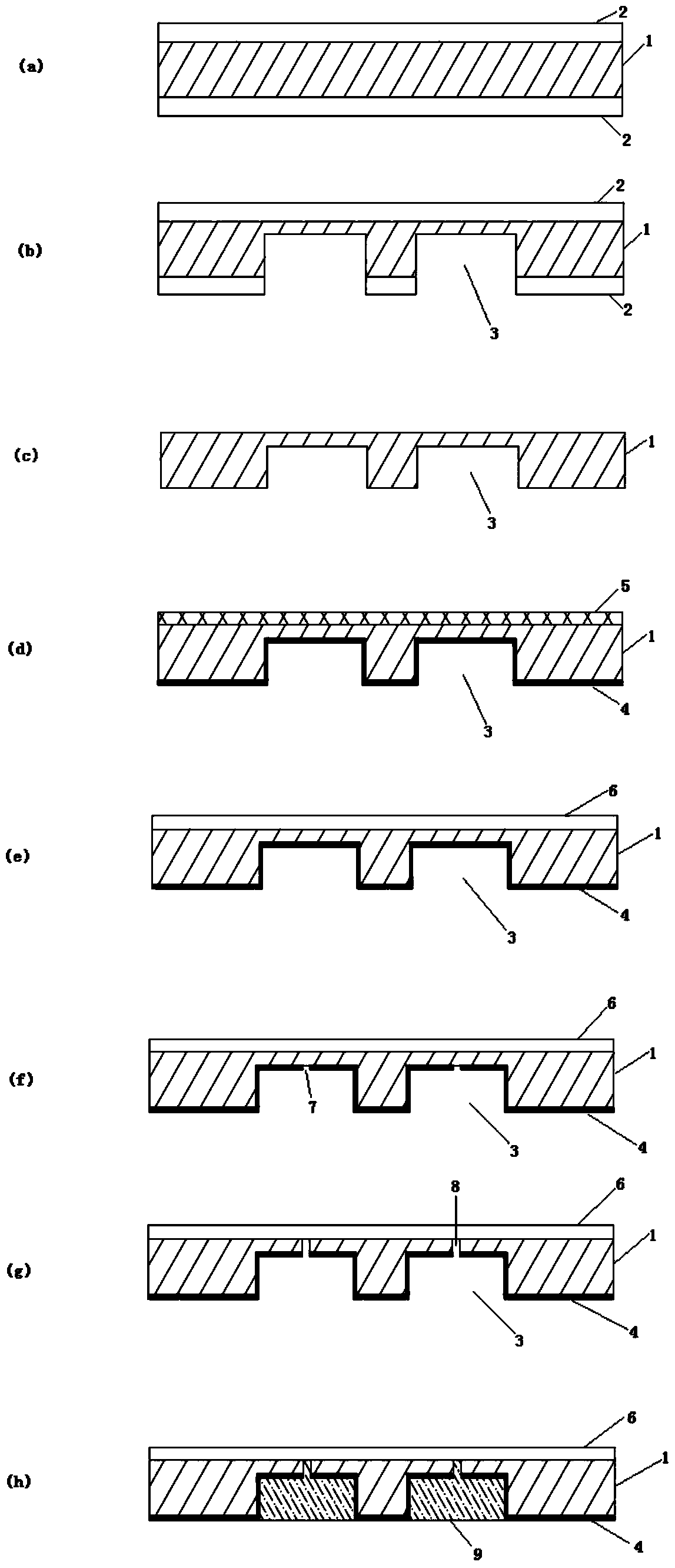
[0050] The present invention also provides a method for preparing the metal casing of the above-mentioned communication device, wherein the method includes the following steps:
[0051] 1) the step of forming the first protective layer on the surface of the metal substrate;
[0052] 2) a step of forming a groove penetrating through the first protective layer and part of the metal substrate on the inner surface side of the metal substrate;
[0053] 3) removing the first protective layer and forming a second protective layer on the inner surface of the metal substrate;
[0054] 4) a step of forming a decorative layer on the outer surface of the metal substrate;
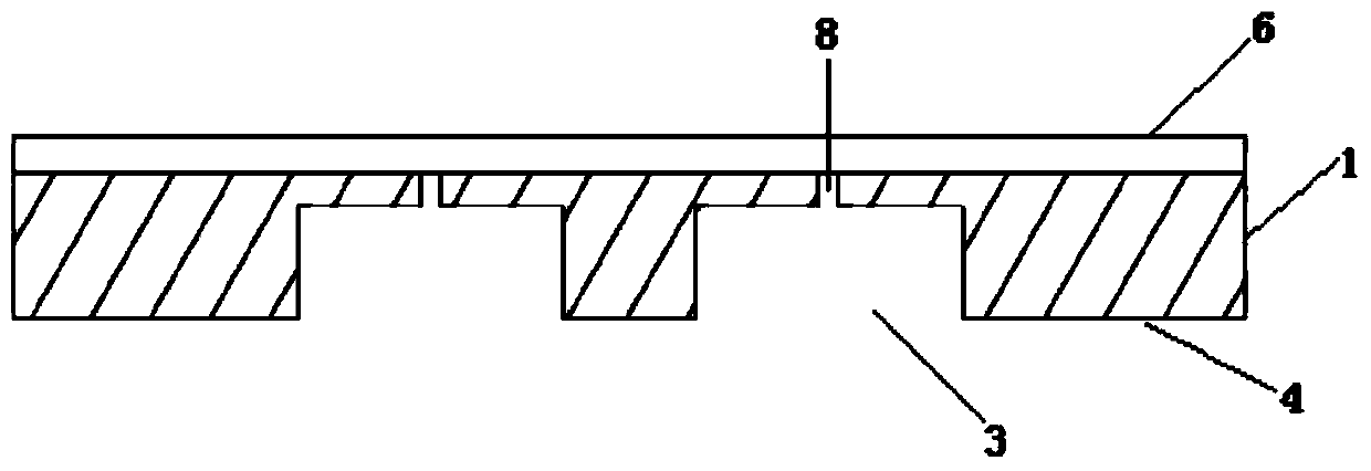
[0055] 5) A step of forming a slit through the metal substrate at the bottom of the groove.
[0056] The above-mentioned steps of the present invention will be described in detail below.
[0057] Step 1): the step of forming the first protective layer on the surface of the metal substrate
[0058] In the present i...
Embodiment 1
[0121] 1) Aluminum alloy (purchased from Dongguan Gangxiang Metal Materials Co., Ltd., grade 6063, thickness 0.4mm) was cut into a size of 15mm x 80mm as the metal substrate. After spraying 5680 series UV ink (purchased from Shenzhen Wanjiayuan Fine Chemical Technology Co., Ltd., the same below) on the surface of the metal substrate, and then baking at 80°C for 25 minutes, UV exposure was carried out (the exposure condition was 2 minutes, The light intensity is 800mJ / cm 2 ), forming two 2mm wide substrate strips, wherein the length of the substrate strips is 75mm, and the distance between two adjacent substrate strips is 3mm. In addition, the thickness of the formed UV ink layer was 20 μm.
[0122] 2) Etching the metal substrate obtained in step 1) with an acid etching solution, and then etching with an alkaline etching solution. Wherein, the acidic etching solution is a mixed solution of 550g of ferric chloride, 30g of hydrochloric acid and 100g of water, and the etching co...
Embodiment 2
[0131] 1) Aluminum alloy (purchased from Dongguan Gangxiang Metal Materials Co., Ltd., grade 6063, thickness 0.4mm) was cut into a size of 15mm x 80mm as the metal substrate. After spraying 5680 series UV ink on the surface of the metal substrate, and then baking at 80°C for 25 minutes, carry out ultraviolet exposure (exposure time is 2min, light intensity is 800mJ / cm 2 ), forming two 3mm wide substrate strips, wherein the length of the substrate strips is 75mm, and the distance between two adjacent substrate strips is 3mm. In addition, the thickness of the formed UV ink layer was 20 μm.
[0132] 2) After the metal substrate obtained in step 1) is etched with an acidic etchant, it is then etched with an alkaline etchant. Wherein, the acidic etching solution is a mixed solution of ferric chloride of 550g, hydrochloric acid of 30g and water of 100g, and the condition of described acidic etching solution etching is: temperature is 30 ℃, time is 10 minutes; The etching solution ...
PUM
 Abstract
Description
Claims
Application Information
 - R&D
- Intellectual Property
- Life Sciences
- Materials
- Tech Scout
- Unparalleled Data Quality
- Higher Quality Content
- 60% Fewer Hallucinations
Browse by: Latest US Patents, China's latest patents, Technical Efficacy Thesaurus, Application Domain, Technology Topic, Popular Technical Reports.
© 2025 PatSnap. All rights reserved.Legal|Privacy policy|Modern Slavery Act Transparency Statement|Sitemap|About US| Contact US: help@patsnap.com


