Test tube cleaning and drying device for chemical tests

A technology for drying devices and chemical experiments, applied in drying, drying machines, heating devices, etc., can solve problems such as inability to store immediately and incomplete cleaning of test tubes, so as to improve cleaning efficiency and cleanliness, save electric energy, and improve The effect of drying efficiency

Inactive Publication Date: 2017-02-01
赵靖宇
View PDF9 Cites 29 Cited by
  • Summary
  • Abstract
  • Description
  • Claims
  • Application Information

AI Technical Summary

Problems solved by technology

[0006] The technical task of the present invention is to provide a test tube cleaning and drying device for chemical experiments to solve the problem that the test tubes are not fully cleaned and cannot be stored immediately after cleaning.

Method used


Image

  • Test tube cleaning and drying device for chemical tests
  • Test tube cleaning and drying device for chemical tests
  • Test tube cleaning and drying device for chemical tests

Examples


Embodiment 1

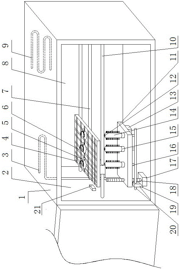
[0030] as attached figure 1 And attached figure 2 As shown, the chemical experiment test tube cleaning and drying device of the present invention includes a casing 1, and the inside of the casing 1 is divided into a cleaning chamber 2 and a drying chamber 8 connected to the left and right, and a cleaning device is fixed in the cleaning chamber 2. A drying device is fixed in the drying chamber 8, and a test tube moving device is fixed in the cabinet 1. A grid-shaped test tube fixing plate 4 is fixed on the test tube moving device, and the test tube moving device can drive the test tube fixing plate 4 in the cleaning chamber. Chamber 2 and the drying chamber 8 slide, and a plurality of scrubbing holes 6 are provided on the test tube fixing plate 4, and a test tube fixing clip 5 is fixed at each scrubbing hole 6 on the test tube fixing plate 4, and the test tube fixing clip 5 includes The column and the U-shaped clamp fixed on the top of the column, the column is vertically fix...

Embodiment 2

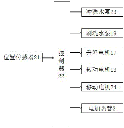
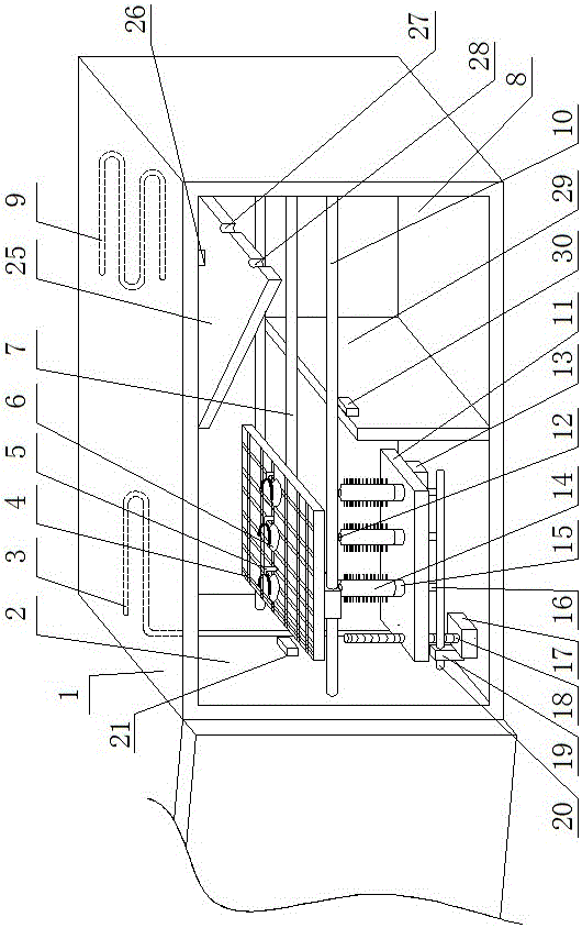
[0044] attached image 3 And attached Figure 4 As shown, this embodiment is a further improvement on the basis of Embodiment 1. The difference between this embodiment and Embodiment 1 is that a partition is provided between the cleaning chamber 2 and the drying chamber 8, and the partition includes an upper Partition 25 and lower partition 29, lower partition 29 is vertically fixed in casing 1 and is positioned at the below of test tube moving device, and the top of upper partition 25 is hinged on the top wall of casing 1 by hinge, upper A rotary drive device is connected between the partition plate 25 and the top wall of the chamber. The rotary drive device can drive the rotation of the upper partition plate 25 to realize the on-off of the cleaning chamber 2 and the drying chamber 8. The upper end of the lower partition plate 29 A lower limit sensor 30 is arranged on the top, and an upper limit sensor 26 is arranged on the top wall of the box body 1. The rotary drive device...


PUM


Abstract

The invention discloses a test tube cleaning and drying device for chemical tests and belongs to the field of test tube cleaning and drying devices. The technical problems that test tubes cannot be cleaned thoroughly and cannot be stored immediately after being cleaned are solved. As for the structure, the test tube cleaning and drying device comprises a box body. The interior of the box body is divided into a cleaning cavity and a drying cavity, and the cleaning cavity communicates with the drying cavity in the left-right direction. A test tube moving device is fixed in the box body. A grid-shaped test tube fixing plate is fixed to the test tube moving device. A plurality of brushing holes are formed in the test tube fixing plate. A test tube fixing clip is fixed in the position of each brushing hole in the test tube fixing plate. The cleaning device comprises a flushing device and a brushing device. The flushing device is fixed to the position above the test tube fixing plate. The brushing device is fixed below the test tube fixing plate. A drying device body is fixed to the position above the test tube fixing plate. The test tube moving device, the flushing device, the brushing device and the drying device body are all connected to a controller. By the adoption of the test tube cleaning and drying device, the test tubes can be cleaned thoroughly and dried.

Description

technical field [0001] The invention relates to the field of test tube cleaning and drying devices, in particular to a test tube cleaning and drying device for chemical experiments. Background technique [0002] The test tube is an indispensable experimental tool in the chemical experiment. After the chemical experiment, the test tube needs to be cleaned for future use and storage. In the existing test tube cleaning, a test tube brush is usually used for individual cleaning. When the test tube used in the experiment process is more For a long time, this cleaning method is inconvenient, and usually there is still water in the cleaned test tube, which cannot be stored immediately. [0003] The Chinese patent with the publication number CN 205673321 U published on November 9, 2016 proposes a test tube cleaning device for student chemistry, including a test tube holder, on which a number of test tube grooves are provided; both sides of the test tube holder are provided with The...

Claims


Application Information

Patent Timeline
Patent Type & Authority Applications(China)
IPC IPC(8): B08B9/093B08B9/087F26B23/06
CPCB08B9/0808B08B9/0813F26B23/06
Inventor 赵靖宇
Owner 赵靖宇
Why Eureka
Try Eureka