
Wing generating larger lift force and aircraft

A wing and lift technology, applied in the field of aircraft, can solve the problems of low lift, pressure difference, restricting the development of aircraft, etc., and achieve the effect of increasing the load and increasing the flight speed.

Inactive Publication Date: 2017-02-01
朱晓义
View PDF7 Cites 4 Cited by
  • Summary
  • Abstract
  • Description
  • Claims
  • Application Information

AI Technical Summary

Problems solved by technology

[0002] It has been more than one hundred years since the aircraft appeared, and the only source of lift for fixed-wing aircraft is the wing, and the upper and lower surfaces of the wing are arc surfaces and the difference in the fluid path between the plane is very small, so the pressure difference and lift generated are also Small, seriously restricting the future development of aircraft

Method used


Image

  • Wing generating larger lift force and aircraft
  • Wing generating larger lift force and aircraft

Examples


Embodiment 1

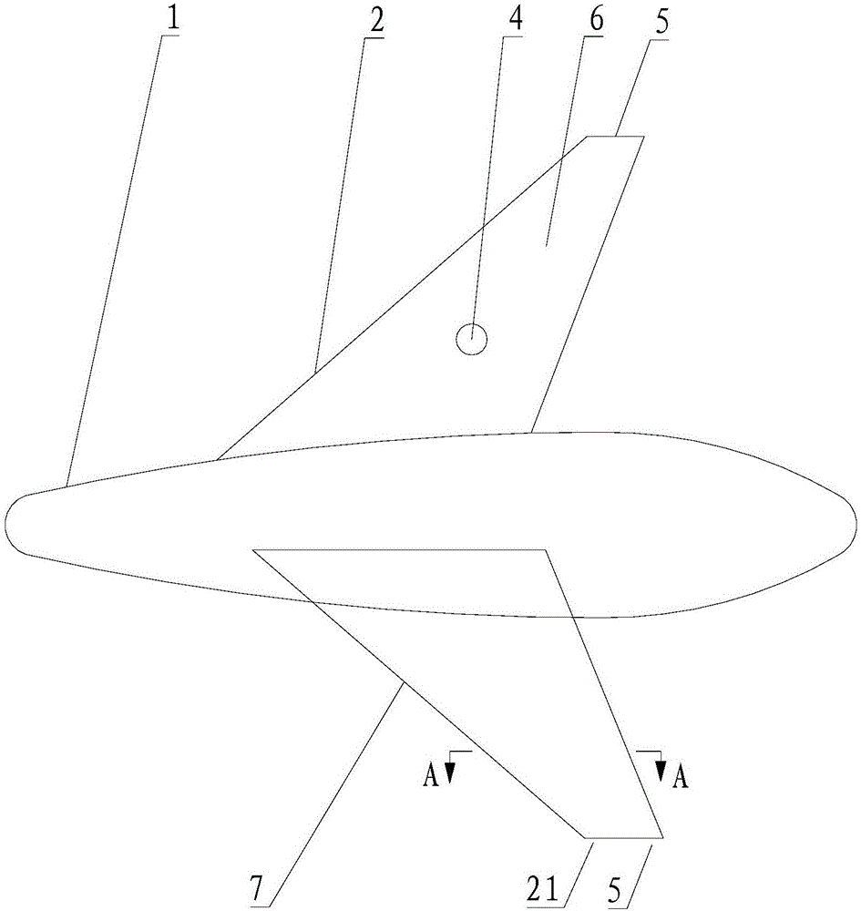
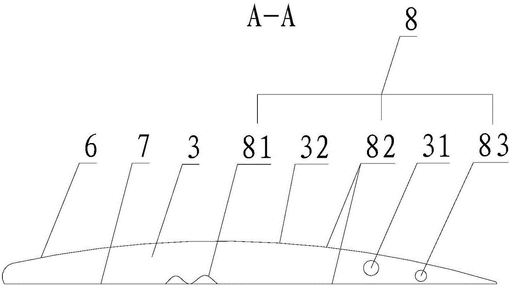
[0041] Please refer to figure 1 and figure 2 Shown, embodiment one of the present invention is:

[0042] An aircraft, comprising a fuselage 1 and a wing 2, a fluid channel 3 is provided inside the wing 2, and a plurality of air vents 4 are arranged on the upper surface of the wing 6 to communicate with the fluid channel 3 inside the wing 2, and the fluid channel 3 communicates with the exhaust port 5 provided on the end surface of the tail end of the wing, and a turbulence device 8 extending the passage of the fluid is provided in the fluid channel 3, and the turbulence device 8 is: a concave-convex turbulence on the inner surface of the fluid channel One or more components of the surface 81, the spiral spoiler surface 82, and the spiral spoiler 83.

[0043] Owing to being provided with spoiler 8 in fluid passage 3, the path that makes fluid pass through fluid passage 3 increases, and flow velocity becomes faster, faster than the flow velocity that fluid passes through wing...

Embodiment 2

[0056] Please refer to figure 1 and figure 2 Shown, embodiment two of the present invention is:

[0057] A kind of aircraft, and embodiment one difference is: remove spoiler 8; Be located at a plurality of air vents 4 of wing upper surface 6 through the fluid channel 3 inside wing 2 and tail exhaust port 5 communicate, make fluid The flow velocity between the length direction of the upper surface 6 of the wing and the width direction of the lower surface 7 is different, and the resulting pressure difference is the greater source of lift for the wing 2 .

[0058] When the aircraft of this embodiment is flying, a plurality of air vents 4 evenly arranged on the entire wing upper surface 6 lead the fluid passing through the wing upper surface 6 into the fluid channel 3, and then exhaust air from the air outlet 21 arranged at the wing tail. The port 5 is discharged outward, so that the fluid passes through the wing length direction of the high-speed fluid layer 32 formed jointly...


PUM


Abstract

The invention relates to a wing generating larger lift force and an aircraft. A plurality of air vents formed in the upper surface of the wing communicate with air outlets in the tail of the wing through fluid channels in the wing, thus the flowing speed of fluid in the length direction of the upper surface of the wing and the flowing speed in the width direction of the lower surface of the wing are different, and the generated pressure difference is a larger lift force source for the swing. According to the wing generating larger lift force and the aircraft, the wing structures of various existing aircrafts are changed little, while the lift force source many times larger than that of a traditional wing is generated, the load capacity of the aircraft is increased instantly and significantly, the flying speed is increased significantly, the flying radius is increased in multiples, thus the high-speed energy-saving aircraft is produced, and a completely novel direction is opened for the development of aircrafts in the future.

Description

technical field [0001] The invention relates to the technical field of aircraft, in particular to a wing and an aircraft that generate greater lift. Background technique [0002] It has been more than one hundred years since the aircraft appeared, and the only source of lift for fixed-wing aircraft is the wing, and the upper and lower surfaces of the wing are arc surfaces and the difference in the fluid path between the plane is very small, so the pressure difference and lift generated are also Small, seriously restricting the future development of aircraft. [0003] The inventor has been authorized Chinese invention patent No. 2008100653341 "A Motion Device" and the invention US Patent No. US 8.448.892B3 "A Flying Saucer with Internally Generated Greater Lift", etc., and proposes a source of lift from the inside. Methods and Apparatus. [0004] On the basis of this, the inventor has studied for many years and found a wing and an aircraft that have little change to the win...

Claims


Application Information

Patent Timeline
IPC IPC(8): B64C21/02
CPCB64C21/025
Inventor 朱晓义
Owner 朱晓义
Learn More