Sag damping cable

A damping and damper technology, applied in the field of structural vibration reduction, can solve the problems of increased main cable tension, low lateral stiffness, structural deformation, etc., and achieve the effects of reducing deformation capacity, increasing energy dissipation capacity, and reducing deformation.

Active Publication Date: 2017-02-01
HUNAN UNIV OF SCI & TECH
View PDF4 Cites 3 Cited by
  • Summary
  • Abstract
  • Description
  • Claims
  • Application Information

AI Technical Summary

Problems solved by technology

[0003] The double-cable composite damping cable eliminates the sag of the main cable, so that it has a greater axial stiffness, and uses the large axial stiffness of the main cable to achieve vibration reduction between two structures that are far apart, but it has the following disadvantages: ( 1) The main cable has a relatively large axial stiffness, because the auxiliary cable sags in the vertical plane, so the vertical stiffness of the main cable and the auxiliary cable is relatively large, while the transverse stiffness is very small, which will occur under the action of transverse wind Larger lateral deformation leads to a significant increase in the tension of the main cable, resulting in a larger deformation of the structure
(2) When the structure vibrates, a periodically changing tensile force will be generated in the axial direction of the main cable and the auxiliary cable. When the change frequency of the tension force is consistent with the natural frequency of the main cable or auxiliary cable, it will cause a large Vibration, which adversely affects structural vibration damping
(3) The structure of the composite damping cable is relatively complex, the length and installation position of the boom must be accurately calculated and installed in advance, and it is difficult to change later

Method used


Image

  • Sag damping cable
  • Sag damping cable
  • Sag damping cable

Examples


Embodiment Construction

[0020] The present invention will be further described in detail below in conjunction with the accompanying drawings and embodiments.

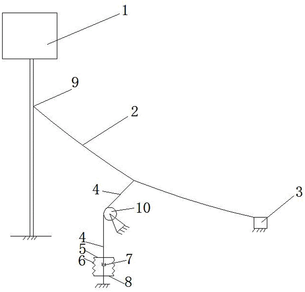
[0021] see figure 1 , taking the vibration reduction of towering structures such as transmission towers as an example, the towering structure vibrates under the action of strong wind (usually the structure swings from side to side), which is simplified as figure 1 The vibrating structure is shown in 1. From figure 1 It can be seen from the figure that the upper end of the main cable 2 is connected to the upper anchor point 9 fixed on the vibrating structure 1, and the lower end of the main cable 2 is connected to the anchorage 3 fixed on the ground. The main cable 2 sags or deforms laterally under the action of its own gravity or wind force, and deviates from the straight line connecting the upper and lower anchor points of the main cable 2. Generally, the distance from the midpoint of the main cable 2 to the straight line is the largest,...


PUM


Abstract

The invention discloses a sag damping cable which comprises a main cable. The upper end of the main cable is connected with an upper anchoring point fixedly connected with a structure, the lower end of the main cable is connected with an anchor fixed to the ground, a suspension cable is fixedly connected in the main cable and is roughly perpendicular to the main cable, and the lower end of the suspension cable is connected with an upper beam. A lower beam is fixedly connected with the ground through another suspension cable or directly connected with the ground. A damper is installed between the upper beam and the lower beam. The form of combining the single main cable, the suspension cable and the damper is adopted, the main cable vibrates through structural vibration, the sag of the main cable varies periodically with the structural vibration, the damper is driven to consume energy by utilizing periodic variations of the sag of the main cable, and thus the structural vibration is restrained.

Description

technical field [0001] The invention belongs to the technical field of structure damping, and in particular relates to a sag damping cable. Background technique [0002] Viscous dampers are widely used in structural wind and earthquake resistance because of their strong energy dissipation capacity, reliable operation, good robustness, convenient installation and low cost. However, when the viscous damper performs energy dissipation and vibration reduction on structural vibration, it needs to be installed at a point near the structure that has relative motion, and the piston rod of the damper and the cylinder are driven to reciprocate through the relative motion between the structure and the point. The relative motion dissipates energy, thereby reducing the vibration of the structure. Under the action of earthquake or wind, super high-rise buildings will experience relatively large lateral vibration (or vibration). The existing vibration reduction technology uses Tune mass d...

Claims


Application Information

Patent Timeline
Patent Type & Authority Applications(China)
IPC IPC(8): E04B1/98E04H9/02E04H9/14
CPCE04H9/021E04H9/14
Inventor 禹见达张湘琦于浩禹蒲阳
Owner HUNAN UNIV OF SCI & TECH
Why Eureka
Try Eureka