An engine air compressor resonant cavity

A resonant cavity and air compressor technology, which is applied in the resonant cavity of the engine air compressor to improve the oil leakage and intake noise of the engine air compressor, can solve the problems of large space occupation and limited noise reduction ability, and increase the sound wave reflection Effects of harmonizing sound energy loss, reducing discharge speed, and reducing noise

Active Publication Date: 2018-12-07
DONGFENG COMML VEHICLE CO LTD
View PDF7 Cites 0 Cited by
  • Summary
  • Abstract
  • Description
  • Claims
  • Application Information

AI Technical Summary

Problems solved by technology

[0006] The purpose of the present invention is to overcome the problems of limited noise reduction ability, large space occupation, and unavoidable excessive oil leakage in the air compressor in the prior art, and provide an air compressor with remarkable noise reduction effect, compact structure, and effective air compressor Too much oil in the engine air compressor resonant cavity

Method used


Image

  • An engine air compressor resonant cavity
  • An engine air compressor resonant cavity

Examples


Embodiment 1

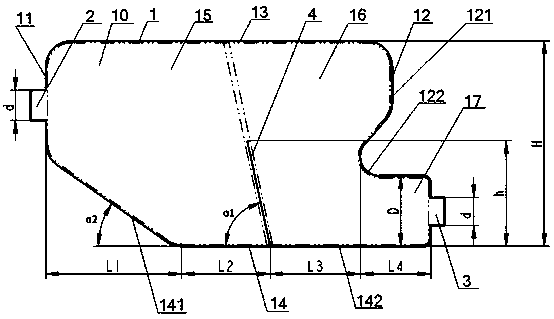
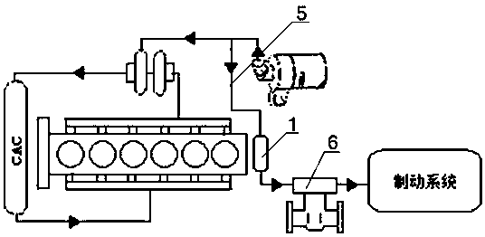
[0036] see figure 1 , figure 2, a resonant cavity of an engine air compressor, the resonant cavity 1 is a box structure, and its volume is at least 5 times the displacement of the air compressor 6, and the air intake side 11 of the resonant cavity 1 is provided with a The air inlet 2 communicated with the air intake pipe 5 of the compressor, the exhaust side 12 of the resonant cavity 1 is provided with the exhaust port 3 communicated with the air intake of the air compressor 6, and the air inlet 2 is close to the top surface of the resonant cavity 1 13, the exhaust port 3 is set near the bottom surface 14 of the resonant cavity 1, and the interior of the resonant cavity 1 is provided with a partition 4, which divides the inner cavity 10 of the resonant cavity 1 into an air intake cavity 15, an exhaust gas Cavity 16, the bottom end of partition plate 4 is fixedly connected with bottom surface 14, there is a gap between the top end of partition plate 4 and top surface 13, and ...


PUM


Abstract

The invention provides a resonant cavity of an air compressor of an engine. The resonant cavity is of a box structure. The capacity of the resonant cavity is at least 5 times as large as the gas displacement of the air compressor. The air intake side of the resonant cavity is provided with an air inlet communicating with an air intake pipe of the air compressor. The exhaust side of the resonant cavity is provided with an exhaust port communicating with an air suction port of the air compressor. The air inlet is close to the top face of the resonant cavity. The exhaust port is close to the bottom face of the resonant cavity. A partition plate is arranged inside the resonant cavity. The bottom end of the partition plate is fixedly connected with the bottom face. A gap is reserved between the top end of the partition plate and the top face. A first included angle is formed between the partition plate and the bottom face and is smaller than or equal to 90 degrees. The resonant cavity of the air compressor of the engine can prevent that too much oil is pumped into a cylinder of the air compressor and can also significantly lower noise.

Description

technical field [0001] The invention belongs to the technical field of automobile engines, and in particular relates to a resonant cavity of an engine air compressor, which is suitable for improving the oil blow-by and intake noise of the engine air compressor. Background technique [0002] Automobile engine air compressor is a key component of automobile braking system, its function is to provide and maintain air with a certain pressure. At present, most automobile engine air compressors use reciprocating piston type. In the actual working process of this type of air compressor, there will usually be too much oil leakage in the air compressor due to factors such as excessive intake resistance or large intake pressure fluctuations. And the problem of high intake noise, especially in the process of rapid acceleration, it is more likely to cause oil leakage in the air compressor. Excessive oil leakage from the air compressor will not only increase the oil consumption of the e...

Claims


Application Information

Patent Timeline
Patent Type & Authority Patents(China)
IPC IPC(8): F04B39/00F04B39/02
CPCF04B39/0066F04B39/0088F04B39/02
Inventor 向辉陈伟建陈功军康丽丽胡国强
Owner DONGFENG COMML VEHICLE CO LTD
Why Eureka
Try Eureka