Blower fan feature multipoint pressure synchronous measurement test system

A technology of synchronous measurement and test system, applied in the pressure difference measurement between multiple valves, transmission system, measurement device, etc., can solve the problems of low accuracy, low efficiency, large workload, etc., to improve the test accuracy and improve the test efficiency

Active Publication Date: 2017-02-01
中氢(湖南)氢能装备有限公司
View PDF6 Cites 6 Cited by
  • Summary
  • Abstract
  • Description
  • Claims
  • Application Information

AI Technical Summary

Problems solved by technology

According to the national standard flow pressure measurement standard, the flow rate on the round pipe and the square pipe needs to measure the speed of 24 or 30 measuring points (the position of the measuring point established by the national standard) respectively on a section. The common test method is to use Pitot static pressure Although according to the national standard, the speed and pressure value of each point is tested point by point, and the arithmetic mean value of all measuring points is multiplied by the cross-sectional area to obtain the flow rate, and the arithmetic mean value of the pressure of all measuring points is taken as the pressure value. This method is inefficient and difficult to operate. It is cumbersome, the data measurement is not simultaneous, the accuracy is not high, the data needs to be manually read and recorded, and the workload is heavy

Method used


Image

  • Blower fan feature multipoint pressure synchronous measurement test system
  • Blower fan feature multipoint pressure synchronous measurement test system
  • Blower fan feature multipoint pressure synchronous measurement test system

Examples


Embodiment Construction

[0016] Below in conjunction with accompanying drawing and embodiment the present invention will be further described:

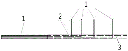
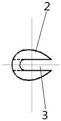
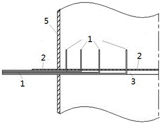
[0017] The fan characteristic multi-point pressure synchronous measurement and testing system includes a miniature total pressure tube 1, a support rod 2, and a test tube. There are grooves on the wall and holes on the other side of the pipe wall. The number of diameters, positions and the number of test points distributed on each diameter in the test cross-section on the test tube are determined according to the neutral linear method or the Chebechev method , position, the number and position of the support rods 2 in the pipeline test cross-section are the same as the number and position of the diameter, the number and position of the holes are the same as the number and position of the test points on each diameter The same, the number of the miniature full-pressure tube 1 is the same as the number of the holes, one right-angled side of the miniature full-pr...


PUM


Abstract

The invention discloses a blower fan feature multipoint pressure synchronous measurement test system. The system comprises miniaturized impact pipes, support bars and a test pipe, wherein the miniaturized impact pipes are capillary stainless steel pipes appearing to be right-angle-shaped, the pipe wall of one side of each support is provided with grooves, the pipe wall of the other side is provided with holes, the quantities and positions of diameters in a test cross section on the test pipe and the quantities and positions of test points on each diameter are determined according to a log-linear method or a log-Tchebycheff method, one right-angle side of each miniaturized impact pipe successively extend from each hole, the other right-angle sides are successively fixed in the grooves in a superposed mode, the two ends of each support bar are fixed on the pipe wall of the test pipe, four static pressure holes are equally distributed on the pipe wall where the test cross section is disposed, and the end portion of the extending end of each miniaturized impact pipe and the four static pressure holes are disposed on the same test cross section. The system has the following advantages: the test efficiency is improved, the test accuracy is improved, the system has a data collection processing analysis function, and test data is displayed in real time.

Description

technical field [0001] The invention relates to a fan characteristic multi-point pressure synchronous measurement and testing system. Background technique [0002] The EMU is the core equipment of the high-speed railway, and the traction motor is the key component of the EMU. Whether the traction motor located on the bogie of the EMU can work normally determines whether the vehicle can run normally, and is directly related to the reliability and safety of the EMU running on the line. One of the important tasks to ensure the normal operation of the traction motor is to ensure the normal heat dissipation of the traction motor and keep it within the normal operating temperature range. At present, for traction motors of EMUs, considering the efficiency and economy of heat dissipation, the heat dissipation method is mainly forced ventilation heat dissipation. The traction motor cooling system of the EMU is mainly composed of a cooling fan and an air duct. The air volume generat...

Claims


Application Information

Patent Timeline
Patent Type & Authority Applications(China)
IPC IPC(8): G01L13/00H04L12/26
CPCG01L13/00H04L43/00H04L43/04H04L43/50
Inventor 梁习锋刘堂红周丹熊小慧孙博谢素超李颢豪
Owner 中氢(湖南)氢能装备有限公司
Why Eureka
Try Eureka