Wireless transmission-based bidirectional display electroscope

A two-way display and wireless transmission technology, applied in the field of electroscopes, can solve the problems of failure to receive, great impact on hearing and vision, and difficulty in receiving signals, so as to reduce the impact and eliminate misjudgment.

Inactive Publication Date: 2017-02-01
国网安徽省电力有限公司岳西县供电公司 +2
View PDF5 Cites 4 Cited by
  • Summary
  • Abstract
  • Description
  • Claims
  • Application Information

AI Technical Summary

Problems solved by technology

[0003] However, in the actual operation process, electric power maintenance is generally carried out on poles outdoors, and at least two people complete it, the operator and the guardian
During outdoor construction, the surrounding construction environment is unpredictable. For example, when the sun is particularly strong, the operator on the pole may not be able to clearly see the light from the sound and light alarm, and when there is noise in the surrounding When it is larger, the sound from the buzzer cannot be easily heard by the operator. Since the operator working on the pole will not move freely as on the ground, it will be more difficult to receive the signal. In addition to individual factors, there is no It is very likely that a valid and correct signal can be received
Once the correct signal is not received, personal injury or death may occur, with serious consequences
The guardian on the ground cannot see the display of the electroscope because he is too far away from the operator
[0004] The display unit of the electroscope in the prior art transmits information through human vision and hearing, but the external environment has a greater impact on hearing and vision, which easily affects the judgment of electric maintenance personnel during work.

Method used


Image

  • Wireless transmission-based bidirectional display electroscope
  • Wireless transmission-based bidirectional display electroscope
  • Wireless transmission-based bidirectional display electroscope

Examples


Embodiment Construction

[0021] The present invention will be further described below in conjunction with accompanying drawing:

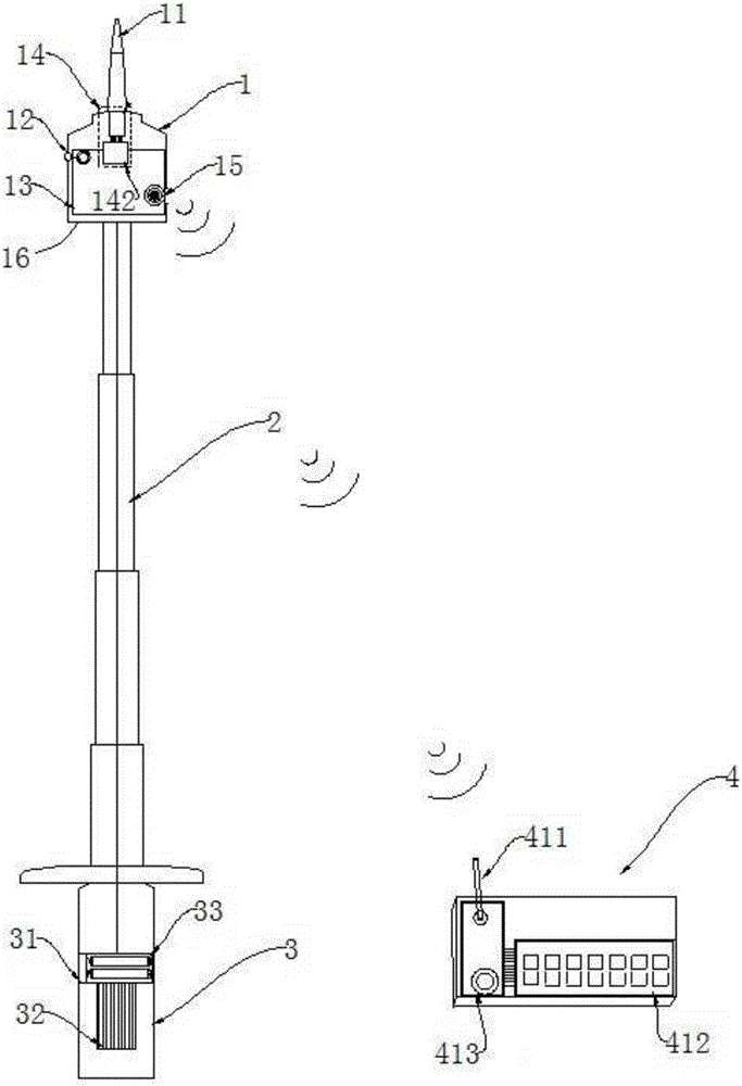
[0022] Such as figure 1 As shown, the two-way display electroscope based on wireless transmission in this embodiment includes an insulating telescopic rod 2, an electroscope body 1 arranged at the top end of the insulating telescopic rod 2, a hand-held part 3 arranged at the bottom end of the insulating telescopic rod 2, and an electroscope. The main body 1 is connected to the telemetry device 4 by radio. The electroscope main body 1 includes a shell 16 installed on the top of the insulating telescopic rod 2. The inside of the shell 16 is provided with a detection device, and the top of the shell 16 is provided with a detection probe 11 connected to the detection device. The detection probe 11 is conical.

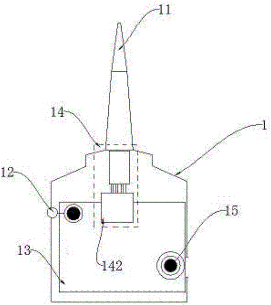
[0023] Such as figure 2 As shown, the detection device includes an integrated circuit board 13, a voltage measurement module 14 and a radio transmission module 15 ins...


PUM


Abstract

The invention relates to a wireless transmission-based bidirectional display electroscope comprising an insulating telescopic rod, an electroscope body arranged on a top end of the insulating telescopic rod, a hand-held part arranged on a bottom end of the insulating telescopic rod and a remote measurement apparatus which is in wireless connection with the electroscope body; the electroscope body comprises an outer shell mounted on a top part of the insulating telescopic rod, a detection device is arranged in the outer shell, a top end of the outer shell is provided with a detection probe connected with the detection device, and the remote measurement apparatus is used for displaying electrification information detected by the electroscope body. The electroscope provided in the invention can be used for bidirectionally displaying electrification conditions; when electrification is detected by the electroscope, alarm signals can be sent from both of the electroscope body and the remote measurement apparatus, an operator can be reminded to be cautious of electric shock danger after an operation supervisor receives the signals; misjudgement caused by individual and environment factors can be prevented via bidirectional display.

Description

technical field [0001] The invention relates to an electroscope, in particular to a two-way display electroscope based on wireless transmission. Background technique [0002] The electroscope is a necessary safety protection equipment for power network maintenance. Before maintenance, first test whether the object of maintenance is live, so as to prevent accidental reasons from energizing the line and causing safety accidents. The existing electroscope mainly includes an electroscope body and an insulating telescopic rod, the electroscope body is connected to the top of the insulating telescopic rod, and the top of the electroscope is provided with a detection probe. When in use, pull out the insulating telescopic rod, hold the handle at the lower end of the telescopic rod, and bring the detection probe close to the wire. If the wire is electrified, the electroscope will send out an audible and visual alarm signal. [0003] However, in the actual operation process, power ma...

Claims


Application Information

Patent Timeline
Patent Type & Authority Applications(China)
IPC IPC(8): G01R19/145G08C17/02
CPCG01R19/145G08C17/02
Inventor 江潜生孙振亮王博王富根汪柏松汪海燕李靖婧甘新华王群兴王龙飞
Owner 国网安徽省电力有限公司岳西县供电公司
Why Eureka
Try Eureka