

High frequency heating device
A high-frequency heating device and technology for heating devices, which are applied to electric heating fuels, lighting and heating equipment, household heating, etc., can solve problems such as rising manufacturing costs, and achieve the effects of eliminating misjudgments, reducing manufacturing costs, and reliably correcting
- Summary
- Abstract
- Description
- Claims
- Application Information
AI Technical Summary
Problems solved by technology
Method used
Image

Examples
Embodiment 1
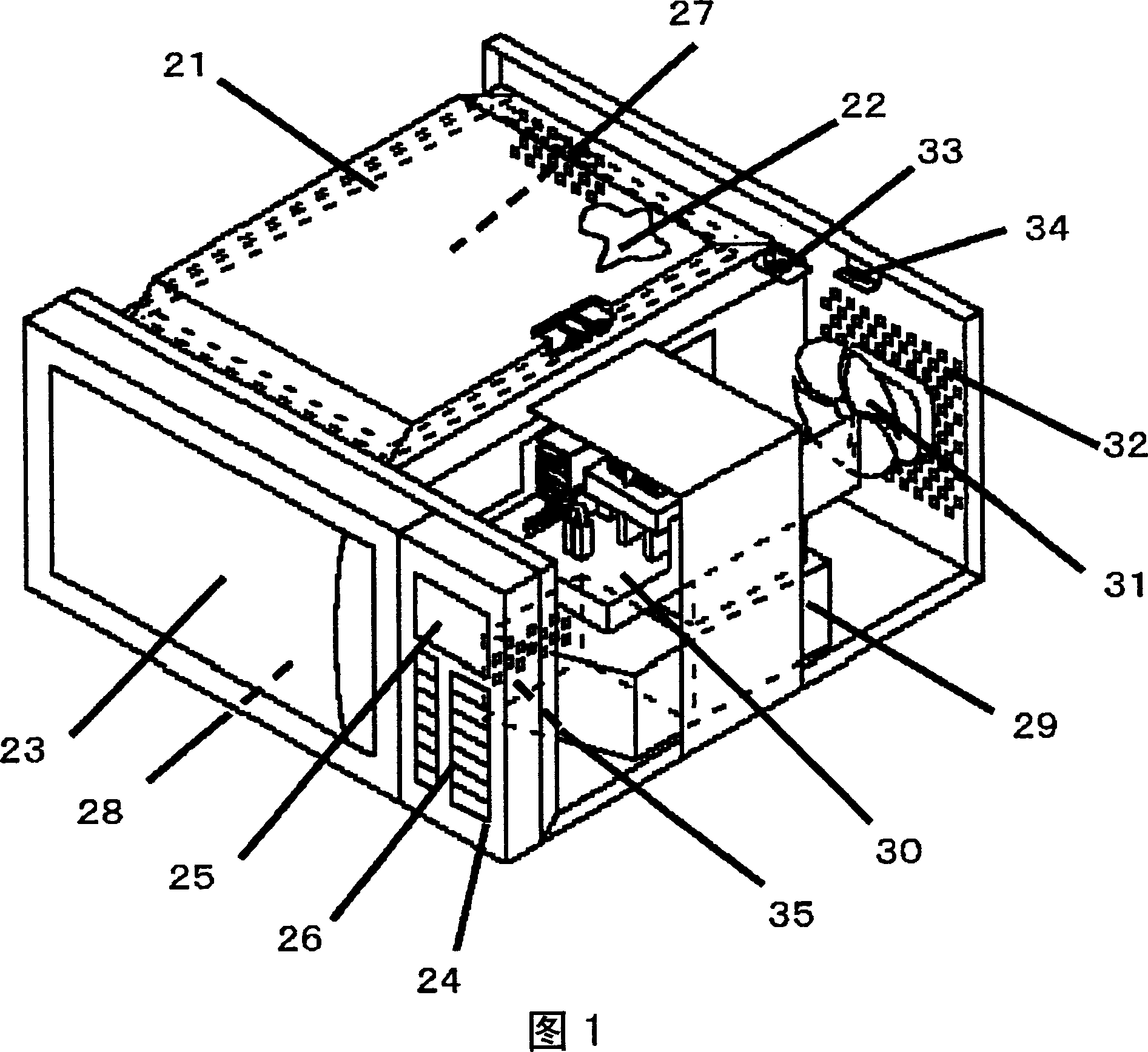
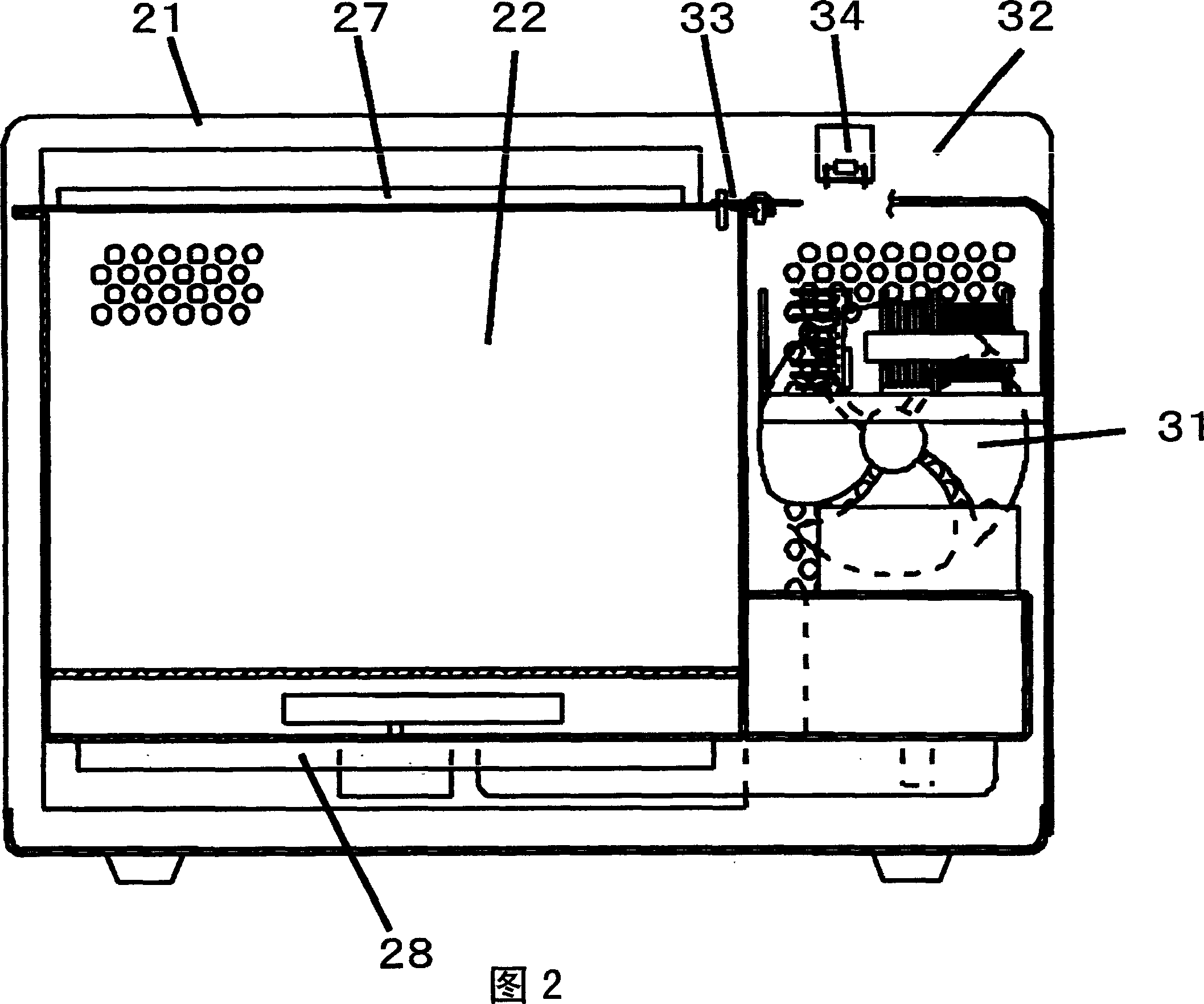
[0029] Fig. 1 is a perspective view of a high-frequency heating device in the first embodiment of the present invention, and Fig. 2 is a cross-sectional view of the high-frequency heating device in the first embodiment of the present invention.
[0030] As shown in FIGS. 1 and 2 , a heating chamber 22 is provided inside the body 21 of the high-frequency heating device, and a door 23 that can be opened and closed freely is provided on the front surface of the heating chamber 22 . The right side of the machine door 23 is provided with an operation panel 24, and the front side of the operation panel 24 is provided with a display unit 25 for displaying temperature and time and an operation key 26 for setting the cooking mode. A planar upper heater 27 is provided inside the top surface of the heating chamber 22 , and a tubular lower heater 28 is provided below the bottom surface. The lower part of the right side of the heating chamber 22 is combined with a magnetron 29 that generat...
Embodiment 2
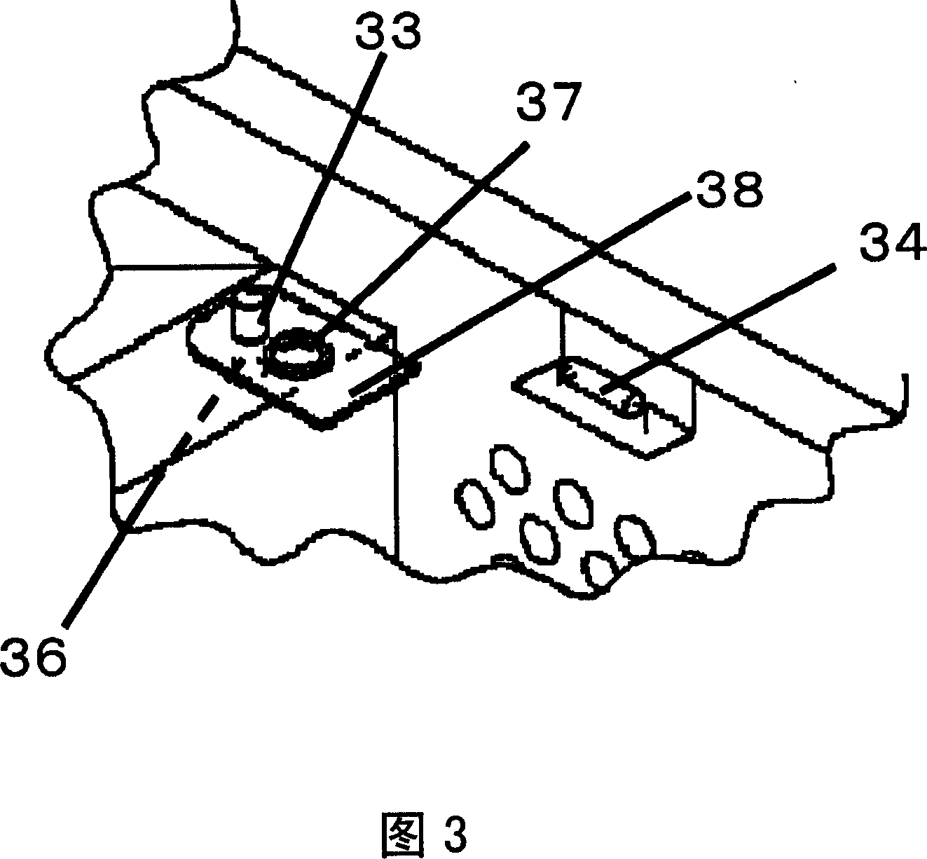
[0039] Fig. 5 is a block diagram showing an electrical configuration in Embodiment 2 of the present invention. Embodiment 2 will be described below in conjunction with FIG. 3 and FIG. 5 . In this embodiment, the following structure is adopted: the heating chamber temperature thermistor 33 installed in the heating chamber 22 and the suction temperature thermistor 34 installed on the back plate 32 are used in combination to control the heating chamber temperature thermistor 33 The temperature is corrected. Specifically, after the heating chamber temperature thermistor 33 and the suction temperature thermistor 34 are connected in series as shown in FIG. 5 , they are connected to the microcomputer on the control circuit board 35 .
[0040] After adopting the above structure, the temperature of the heating chamber temperature thermistor 33 will be affected by the temperature of the intake air temperature thermistor 34, so the temperature change of the intake air temperature thermi...
Embodiment 3
[0043] Fig. 6 is a partial perspective view of a high-frequency heating device in a third embodiment of the present invention. As shown in FIG. 6, an air guide member 40 is provided near the installation portion 37 of the heating chamber temperature thermistor 33. The air guide member 40 is two L-shaped flat plates, one of which has a The air vent 39 is provided on the side with the air vent 39 on the side of the heating chamber 22, and the surface on the side of the cooling fan 31 is open. The action of this air guide member 40 will be described below. Simultaneously with the start of cooking or after a period of time, the cooling fan 31 starts to rotate to suck outside air into the body 21 from the outside of the body 21 to cool the electrical components in the body 21 . However, different from the previous embodiments, this embodiment makes the inflowing outside air rectified before being introduced to the temperature detection plate 37 of the heating chamber temperature t...
PUM
 Abstract
Description
Claims
Application Information