Common mode noise suppression device and noise suppression method for time-difference type fluxgate sensor
A technology of fluxgate sensor and common mode noise, which is applied to the magnetic field measurement and the size/direction of the magnetic field using the principle of magnetic flux control, which can solve the problems of difficult implementation, complex implementation, quantization error, etc., and avoid the data processing process , Improve measurement efficiency and reduce the effect of demanding requirements
- Summary
- Abstract
- Description
- Claims
- Application Information
AI Technical Summary
Problems solved by technology
Method used
Image
Examples
Embodiment 1
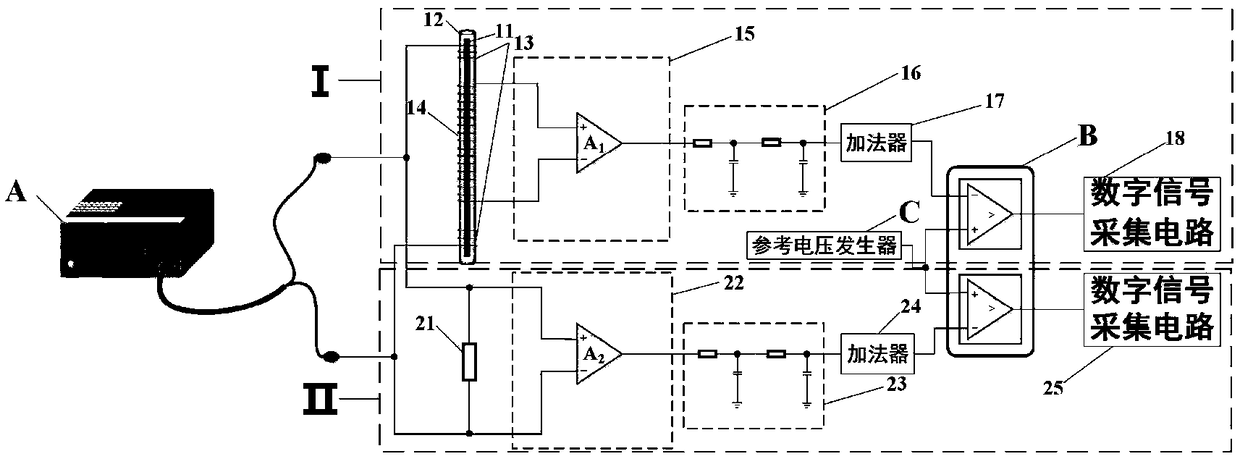
[0037] The device for optimizing the noise performance of a time-difference fluxgate sensor includes a detection circuit I and a reference circuit II. The detection circuit I includes a sensor core 11 placed in a cylindrical core frame 12, an excitation coil 13 is wound at both ends, and is connected to a current signal source A, and an induction coil 14 is wound around the middle part of the cylindrical core frame 12 , the positive and negative poles of the output signal of the induction coil 14 are connected to the preamplifier circuit a15, and the preamplifier circuit a15 is connected to the digital signal acquisition circuit a18 through the second-order low-pass filter circuit a16, the adder circuit a17, and the dual-channel comparator circuit B. connect. The reference circuit II includes a resistor 21 with the same physical characteristics as the induction coil 14. The two ends of the resistor 21 are connected to the current signal source A. The current signal is converte...
Embodiment 2
[0044] The device for optimizing the noise performance of a time-difference fluxgate sensor includes a detection circuit I and a reference circuit II. The detection circuit I includes a sensor core 11 placed in a cylindrical core frame 12, an excitation coil 13 is wound at both ends, and is connected to a current signal source A, and an induction coil 14 is wound around the middle part of the cylindrical core frame 12 , the positive and negative poles of the output signal of the induction coil 14 are connected to the preamplifier circuit a15, and the preamplifier circuit a15 is connected to the digital signal acquisition circuit a18 through the second-order low-pass filter circuit a16, the adder circuit a17, and the dual-channel comparator circuit B. connect. The reference circuit II includes a resistor 21 with the same physical characteristics as the induction coil 14. The two ends of the resistor 21 are connected to the current signal source A. The current signal is converte...
PUM
 Abstract
Description
Claims
Application Information
 - R&D
- Intellectual Property
- Life Sciences
- Materials
- Tech Scout
- Unparalleled Data Quality
- Higher Quality Content
- 60% Fewer Hallucinations
Browse by: Latest US Patents, China's latest patents, Technical Efficacy Thesaurus, Application Domain, Technology Topic, Popular Technical Reports.
© 2025 PatSnap. All rights reserved.Legal|Privacy policy|Modern Slavery Act Transparency Statement|Sitemap|About US| Contact US: help@patsnap.com


