Omnibearing leading-out terminal and leading-out structure of distribution transformer
A technology for distribution transformers and outgoing terminals, which is applied in the directions of transformer/coil connectors, transformer/inductor components, transformer/inductor coils/windings/connections, etc., which can solve the problems of insulating liquid leakage, difficulty in realization, and increased loss, etc. problems, to meet the requirements of product installation and use, reduce the impact of contact heat, and save the effect of cable consumption
- Summary
- Abstract
- Description
- Claims
- Application Information
AI Technical Summary
Problems solved by technology
Method used
Image


Examples
Embodiment approach
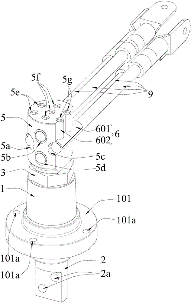
[0034] In order to make it easier for the cold-shrinkable cable sleeve to be placed on the upper part of the insulating mount, and to increase the tightness of the cold-shrinkable cable sleeve to the upper part of the insulating mount to enhance the seal of the cold-shrinkable cable sleeve to the insulating mount As an improved embodiment of the present invention: the upper shape of the above-mentioned insulating mount 1 is a truncated cone shape with a small top and a large bottom.
[0035] As a preferred embodiment of the present invention: an annular boss 101 surrounding the central through hole is provided in the middle of the side wall of the above-mentioned insulating mount 1, and the annular boss 101 is provided with a plurality of installation through holes 101a arranged around the central through hole, and The bottom surface of the annular boss 101 is provided with an annular groove arranged around the central through hole and located inside each installation through h...
PUM
 Abstract
Description
Claims
Application Information
 - R&D
- Intellectual Property
- Life Sciences
- Materials
- Tech Scout
- Unparalleled Data Quality
- Higher Quality Content
- 60% Fewer Hallucinations
Browse by: Latest US Patents, China's latest patents, Technical Efficacy Thesaurus, Application Domain, Technology Topic, Popular Technical Reports.
© 2025 PatSnap. All rights reserved.Legal|Privacy policy|Modern Slavery Act Transparency Statement|Sitemap|About US| Contact US: help@patsnap.com