
An all-round outlet terminal and outlet structure of a distribution transformer

A technology for distribution transformers and outgoing terminals, used in transformer/coil connectors, transformer/inductor components, transformer/inductor coils/windings/connections, etc. It can meet the requirements of product installation and use, reduce the influence of contact heat, and save the amount of cables.

Active Publication Date: 2018-03-09
GUANGDONG BAICHANG ELECTRIC POWER EQUIP CO LTD
View PDF2 Cites 0 Cited by
  • Summary
  • Abstract
  • Description
  • Claims
  • Application Information

AI Technical Summary

Problems solved by technology

[0003] First, the a / b / c phase line and o neutral line of the existing power distribution / buried transformer are installed independently for each phase terminal. The position of the terminal has been fixed before leaving the factory, and it cannot be adjusted on site. Connected, because the cable is hard, it is not easy to be consistent with the direction of the terminal, and it is easy to form stress, resulting in unstable contact. The long-term operation of the contact resistance increases, the contact surface heats up, and the increase in loss also causes the fuel tank to heat up. It will also accelerate the connection between the terminal and the tank cover. Aging of plate seals, causing leakage of insulating liquid;
[0004] Second, the cable needs to adapt to the direction of the terminal. Bending the wiring will increase the cable, increase the cost, and increase the power loss of the cable;
[0005] Third, the a / b / c phase wires and o neutral wire terminals of the existing power distribution / buried transformers are arranged on the fuel tank cover, and the conductors of the connectors are exposed after the outgoing cables are connected, which ensures electrical safety; Even if the insulating shield is used, there is still the problem that the operating state of the terminal cannot be detected with electricity; especially for buried transformer products, it is difficult to achieve IP68 requirements;
[0006] Fourth, the terminals used in the existing power distribution / buried transformers all need wire lug links, requiring on-site crimping, and more process requirements. If there is a problem with the product, relevant tools must also be brought with the on-site processing, and there is more process work.

Method used


Image

  • An all-round outlet terminal and outlet structure of a distribution transformer
  • An all-round outlet terminal and outlet structure of a distribution transformer

Examples


Embodiment approach

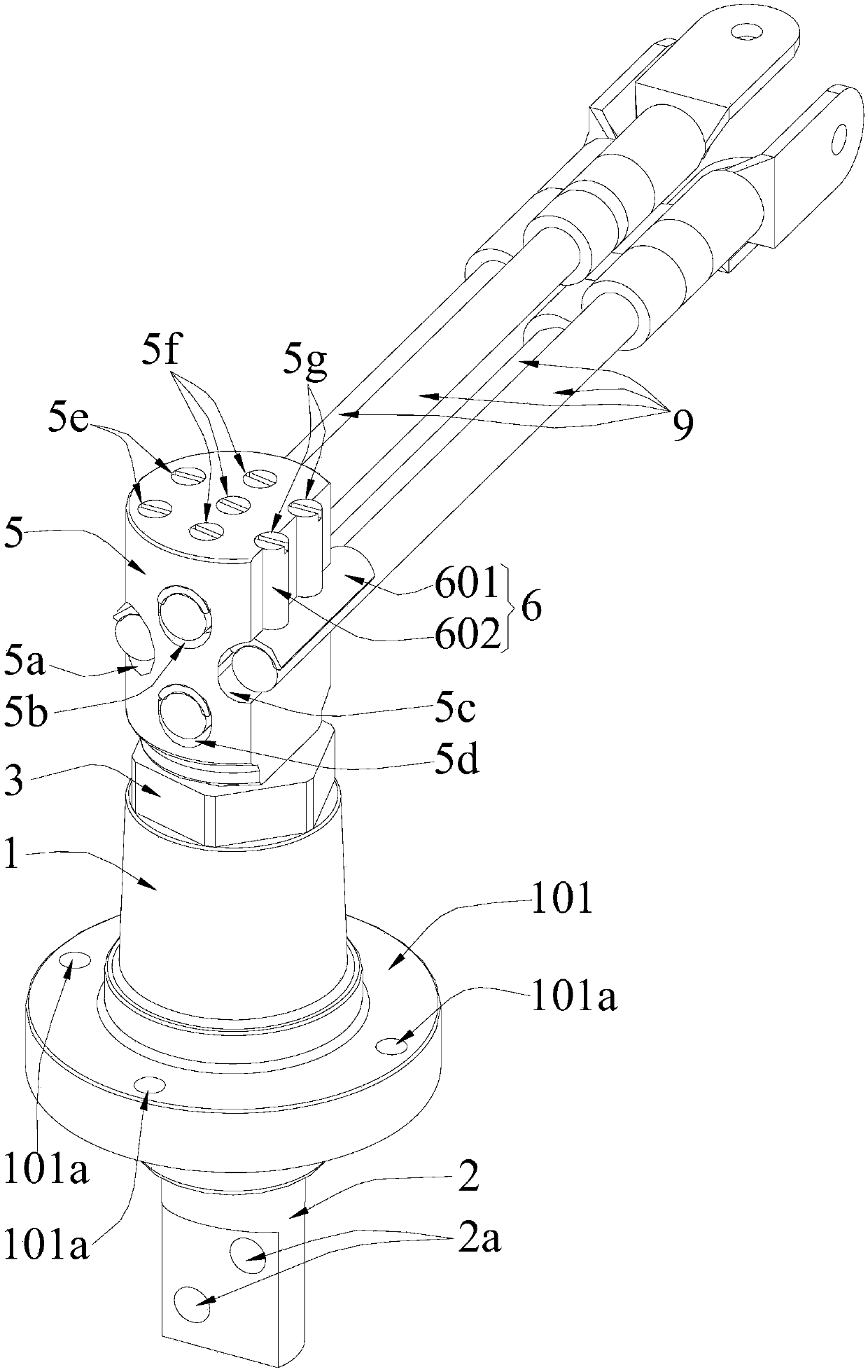
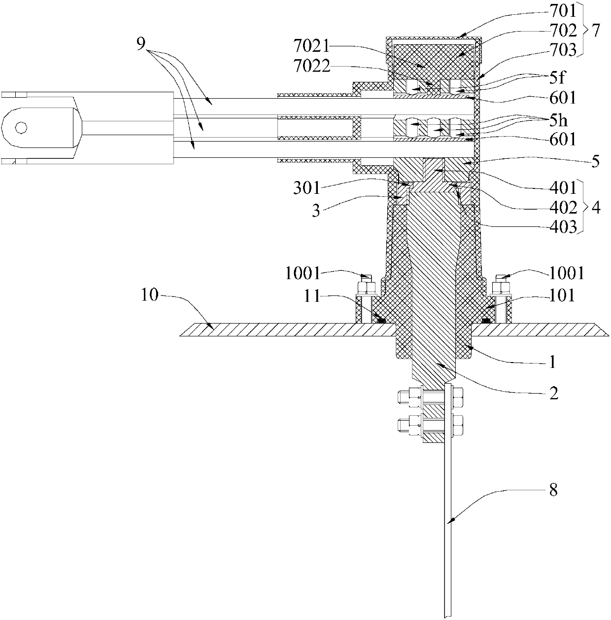
[0034] In order to make it easier for the cold-shrinkable cable sleeve to be placed on the upper part of the insulating mount, and to increase the tightness of the cold-shrinkable cable sleeve to the upper part of the insulating mount to enhance the seal of the cold-shrinkable cable sleeve to the insulating mount As an improved embodiment of the present invention: the upper shape of the above-mentioned insulating mount 1 is a truncated cone shape with a small top and a large bottom.

[0035] As a preferred embodiment of the present invention: an annular boss 101 surrounding the central through hole is provided in the middle of the side wall of the above-mentioned insulating mount 1, and the annular boss 101 is provided with a plurality of installation through holes 101a arranged around the central through hole, and The bottom surface of the annular boss 101 is provided with an annular groove arranged around the central through hole and located inside each installation through h...


PUM


Abstract

The invention discloses an omnibearing leading-out terminal and a leading-out structure of a distribution transformer. The terminal is provided with an insulated mounting seat, a conducting core, a locking nut, a contact terminal, a connecting electrode, a cable connecting mechanism and an insulated external member; the terminal is arranged on an oil tank cover plate of the distribution transformer, when the locking nut is only partially engaged with the cylindrical upper end part of the conducting core, the contact terminal and the connecting electrode positioned on the outside of an oil tank can freely rotate relative to the oil tank cover plate, an installation interface of the connecting electrode can be coincident with the extension direction of an external cable on the site of the distribution transformer, and the external cable does not need to be bent when connected onto the connecting electrode through the cable connecting mechanism, so that the influence of contact heating caused by installation stress is reduced. The direction of connecting the external cable can be adjusted, the terminal has the advantages of convenient mounting, high universality and convenient wiring, the using requirement of product installation can be met to the maximum extent, and the using amount of cables can be saved.

Description

technical field [0001] The invention relates to an omnidirectional outgoing line terminal of a distribution transformer, and an outgoing line structure of a distribution transformer using the omnidirectional outgoing line terminal. Background technique [0002] The a / b / c phase wires and o neutral wires of the existing oil-immersed power distribution / buried transformers go out independently and are listed separately on the cover of the oil tank, which has the following problems: [0003] First, the a / b / c phase line and o neutral line of the existing power distribution / buried transformer are installed independently for each phase terminal. The position of the terminal has been fixed before leaving the factory, and it cannot be adjusted on site. Connected, because the cable is hard, it is not easy to be consistent with the direction of the terminal, and it is easy to form stress, resulting in unstable contact. The long-term operation of the contact resistance increases, the con...

Claims


Application Information

Patent Timeline
Patent Type & Authority Patents(China)
IPC IPC(8): H01F27/29H01F27/32H01R11/11
CPCH01F27/29H01F27/324H01R11/11H01R2201/22
Inventor 刘建南苏颖
Owner GUANGDONG BAICHANG ELECTRIC POWER EQUIP CO LTD
Learn More