Stepping motor

A technology of stepping motors and casings, which is applied in the direction of electrical components, electromechanical devices, electric components, etc., can solve problems such as complex circuit design of drive equipment, inability to apply high-precision products, and unstable output torque of motors, etc., to achieve stable connection, Reduces low-frequency resonance and reduces drive noise

Inactive Publication Date: 2017-02-01
东莞市维斗科技股份有限公司
View PDF5 Cites 4 Cited by
  • Summary
  • Abstract
  • Description
  • Claims
  • Application Information

AI Technical Summary

Problems solved by technology

[0002] At present, the 8mm diameter stepping motor (motor) used for security monitoring is a conventional 18-degree stepping motor (motor). The electrical characteristics of the used motor (motor) mainly include: Max starting frequency, Max continuous Response frequency (Max. slewing frequency), pull-in torque (Pull-in torque), pull-out torque (Pull-out torque), affected by the accuracy of the existing structure, the motor is limited to ordinary precision machine components, and the step accuracy needs to be improved It can only change the excitation mode: change from the original (2-2, two-phase-two-phase) to (1-2, single-two-phase) drive or use a subdivision controller to drive to meet the required requirements; The circuit design of the drive equipment is complex, the cost is high, and it depends on the software to drive and control the motor. The accuracy of the motor is affected by the circuit. The motor output torque is unstable and cannot be applied to high-precision products.
In the process of use, there will be disadvantages such as instability of driving accuracy and reduction of output torque.

Method used


Image

  • Stepping motor
  • Stepping motor
  • Stepping motor

Examples


Embodiment Construction

[0020] The technical solutions in the embodiments of the present invention are clearly and completely described below in conjunction with the accompanying drawings in the embodiments of the present invention. Obviously, the described embodiments are only part of the embodiments of the present invention, not all of them. Based on the embodiments of the present invention, all other embodiments obtained by persons of ordinary skill in the art without making creative efforts belong to the protection scope of the present invention.

[0021] In the following description, a lot of specific details are set forth in order to fully understand the present invention, but the present invention can also be implemented in other ways different from those described here, and those skilled in the art can do it without departing from the meaning of the present invention. By analogy, the present invention is therefore not limited to the specific examples disclosed below.

[0022] Such as figure ...


PUM


Abstract

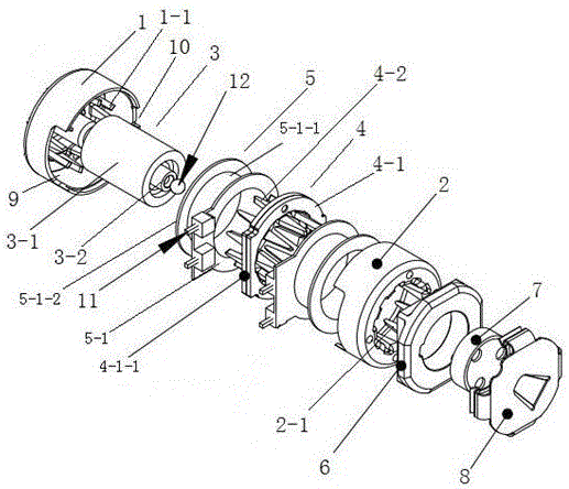
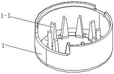
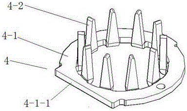
The invention discloses a stepping motor and relates to the technical field of driving devices. The stepping motor comprises an upper motor shell, a lower motor shell, a rotor, two iron cores and two wire winding shafts, wherein the iron cores comprise fixed rings and a number of iron core pole teeth that are arranged along inner circumferences of the fixed rings at an interval, the iron core pole teeth extend axially, the fixed rings of the two iron cores contact directly with each other in such a way that iron core pole teeth on the two iron cores face toward opposite directions, each wire winding shaft correspond to one iron core, and a number of motor shell pole teeth are arranged on inner side walls of the upper motor shell and the lower motor shell at an interval; during assembling operation, first motor shell pole teeth are plugged among iron core pole teeth of one iron core corresponding thereto, and second motor shell pole teeth are plugged among iron core pole teeth of the other iron core corresponding thereto. The stepping motor is advantaged by small magnetic excitation resistance, high control precision, low driving noise, simple structure and the like; the stepping motor is suitable for the field of low frequency and medium-high frequency continuous driving.

Description

technical field [0001] The invention relates to the technical field of driving devices, in particular to a stepping motor with small excitation resistance and high control precision. Background technique [0002] At present, the 8mm diameter stepping motor (motor) used for security monitoring is a conventional 18-degree stepping motor (motor). The electrical characteristics of the used motor (motor) mainly include: Max starting frequency, Max continuous Response frequency (Max. slewing frequency), pull-in torque (Pull-in torque), pull-out torque (Pull-out torque), affected by the accuracy of the existing structure, the motor is limited to ordinary precision machine components, and the step accuracy needs to be improved It can only change the excitation mode: change from the original (2-2, two-phase-two-phase) to (1-2, single-two-phase) drive or use a subdivision controller to drive to meet the required requirements; The circuit design of the drive equipment is complex, the ...

Claims


Application Information

Patent Timeline
Patent Type & Authority Applications(China)
IPC IPC(8): H02K37/02H02K37/14H02K5/04
CPCH02K37/02H02K5/04H02K37/14
Inventor 钟木生杨俊文张竖庭
Owner 东莞市维斗科技股份有限公司
Why Eureka
Try Eureka