Speed reducer with 2K-H type low-range magnetic gear

A magnetic gear and reducer technology, applied in the direction of permanent magnet clutch/brake, electric brake/clutch, electromechanical device, etc., can solve the problems of long design cycle, high design cost, cumbersome design steps, etc., and achieve low machining accuracy requirements , The effect of improving stability and controllability, simplifying the structure of the reducer

Active Publication Date: 2017-02-01
BEIHANG UNIV
View PDF7 Cites 7 Cited by
  • Summary
  • Abstract
  • Description
  • Claims
  • Application Information

AI Technical Summary

Problems solved by technology

However, the design steps of the transmission part of the reducer are cumbersome, such as strength check, fatigue st

Method used


Image

  • Speed reducer with 2K-H type low-range magnetic gear
  • Speed reducer with 2K-H type low-range magnetic gear
  • Speed reducer with 2K-H type low-range magnetic gear

Examples


Embodiment Construction

[0049] The present invention will be further described in detail below in conjunction with the accompanying drawings.

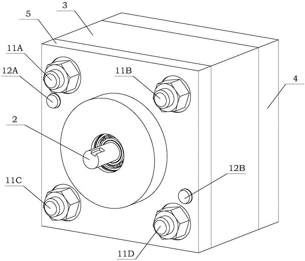
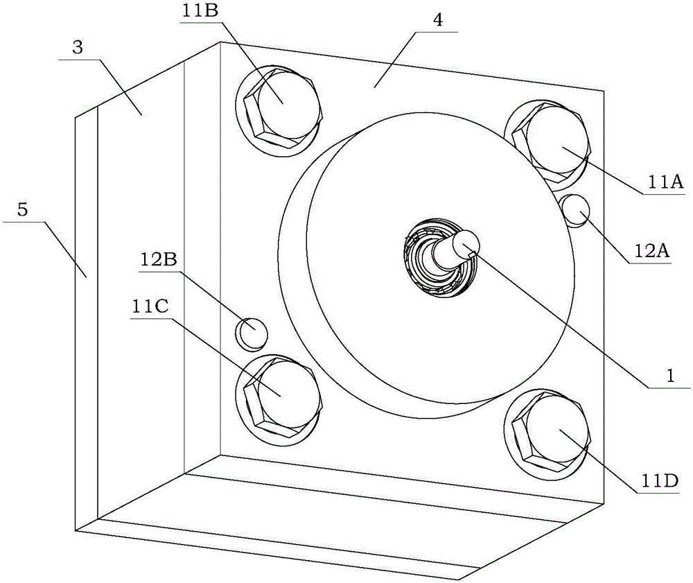
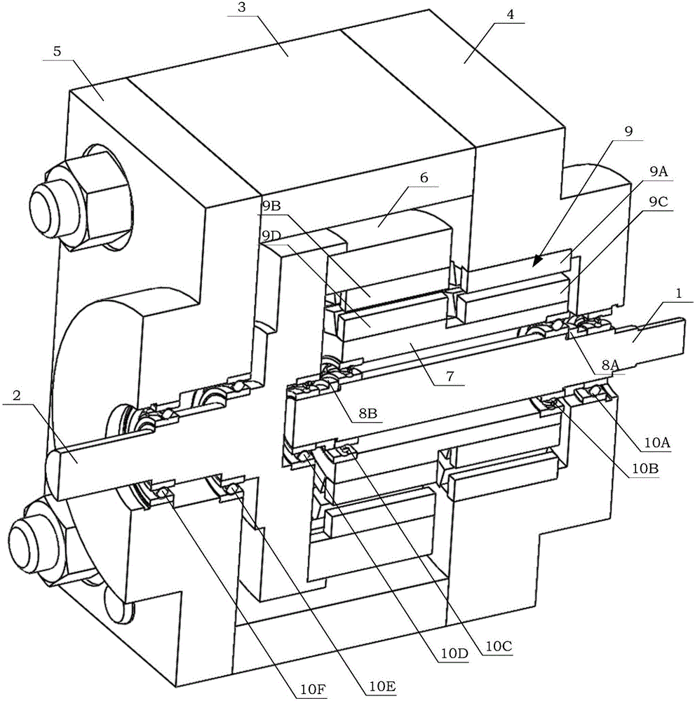
[0050] see figure 1 , Figure 1A , Figure 1B , Figure 1C As shown, the present invention designs a kind of reducer with 2K-H type few extreme difference magnetic gear, and it comprises input shaft 1, output shaft 2, housing 3, end cover (4,5), fixed ring 6, Duplex sleeve 7, shaft sleeves (8A, 8B), magnetic pole assembly 9, deep groove ball bearings (10A-10F), threaded rods (11A-11D) and pins (12A, 12B). In the present invention, the input shaft 1, the output shaft 2, the fixed ring 6, the duplex sleeve 7, the bushings (8A, 8B), the magnetic pole assembly 9 and the deep groove ball bearings (10A-10F) form a deceleration unit. The input shaft 1, the output shaft 2, the casing 3 and the B end cover 5 are processed by metal materials, such as aluminum alloy and stainless steel. A end cap 4, fixed ring 6 and duplex sleeve 7 are processed with magnetically p...


PUM


Abstract

The invention discloses a speed reducer with a 2K-H type low-range magnetic gear. A duplex sleeve (7) is connected with an input shaft (1) through a deep groove ball bearing; a B end cover (5) is connected with an output shaft (2) through a deep groove ball bearing; a fixed ring (6) is fixed on the shaft disc end part of the output shaft; a shell (3) and end covers (4, 5) are fixed through threaded rods (11A-11D) and pins (12A, 12B); a first-level inner layer magnetic block group (9C) is glued on an A section sleeve (7A) of the duplex sleeve (7); a second-level inner layer magnetic block group (9D) is glued on a B section sleeve (7B) of the duplex sleeve (7); a second-level outer layer magnetic block group (9B) is glued on the inner wall of the fixed ring (6); and a first-level outer layer magnetic block group (9A) is mounted in a central through hole of the A end cover (4). According to the speed reducer, the dual-layer magnetic poles are designed on the circumference of the duplex sleeve (7), so that two-level speed reduction without mechanical contact gear transmission is realized; and in addition, the transmission torque and transmission ratio are both relatively high.

Description

technical field [0001] The invention relates to a speed reducer, more particularly, to a speed reducer with a 2K-H type magnetic gear with few extreme differences. Background technique [0002] In recent years, with the rapid development of industrial robots, wind power generation, electric vehicles and other application fields, the significant advantages of magnetic gear transmission technology, such as high efficiency, energy saving, low noise, no pollution, high reliability, no wear, and large transmission ratio, have attracted increasing attention. , At home and abroad, we have begun to achieve technological breakthroughs in mechanical gear transmission in the new magnetic transmission technology. [0003] The reducer is an independent component composed of gear transmission, worm transmission, and gear-worm transmission enclosed in a rigid shell. It is often used as a reduction transmission device between the original moving part and the working machine. It plays the r...

Claims


Application Information

Patent Timeline
IPC IPC(8): H02K49/10
CPCH02K49/102H02K49/106
Inventor 裴旭操宁波王秀丽欧阳若愚
Owner BEIHANG UNIV
Why Eureka
Try Eureka