Filtering patch antenna without additional arrangement of filter circuit, and adjustment method thereof

A patch antenna and filter circuit technology, which is applied in the field of antennas in the field of wireless mobile communications, can solve the problems of large antenna size, deterioration of antenna radiation performance, and large volume, and achieve large loss, good frequency selection characteristics, and large volume Effect

Active Publication Date: 2015-11-18
SOUTH CHINA UNIV OF TECH
View PDF7 Cites 8 Cited by
  • Summary
  • Abstract
  • Description
  • Claims
  • Application Information

AI Technical Summary

Problems solved by technology

The utility model with the publication number CN201812933U, "Integrated Filter Antenna", adopts the first scheme of adding an external circuit, which will bring additional filtering loss, and the overall realization volume is relatively large; the research team of Southeast University adopts the second scheme Based on the dielectric substrate integrated waveguide solution, a series of filter antennas have been made, but they all work in the X-band (10GHz), Ku-band (14.4GHz), and Ka-band (38GHz) above 10GHz, and there is no suitable work below 3GHz. Filter antenna covering 4G-LTE communication frequency band (such as 2.3-2.7GHz) and wireless local area network WLAN communication frequency band (2.4GHz); invention patent of South China University of Technology, publication number CN102570020A, "A kind of squareness with good and stopband bandwidth controllable "Ultra Wideband Notch Antenna", the third scheme is adopted to realize the filter antenna with band-rejection characteristics in the UWB frequency band (3.1-10.6GHz); while the fourth scheme is adopted, the frequency selective surface is easy to cause antenna radiation Performance deterioration, and the electrical size of the cavity is several times the wavelength, resulting in a larger antenna size

Method used


Image

  • Filtering patch antenna without additional arrangement of filter circuit, and adjustment method thereof
  • Filtering patch antenna without additional arrangement of filter circuit, and adjustment method thereof
  • Filtering patch antenna without additional arrangement of filter circuit, and adjustment method thereof

Examples


Embodiment Construction

[0030] The technical details of the present invention will be described clearly and in detail below in conjunction with the drawings in the embodiments of the present invention, and the described embodiments are only some of the embodiments of the present invention, not all of them. Based on the embodiments of the present invention, other embodiments obtained by persons of ordinary skill in the art without making creative efforts all belong to the protection scope of the present invention.

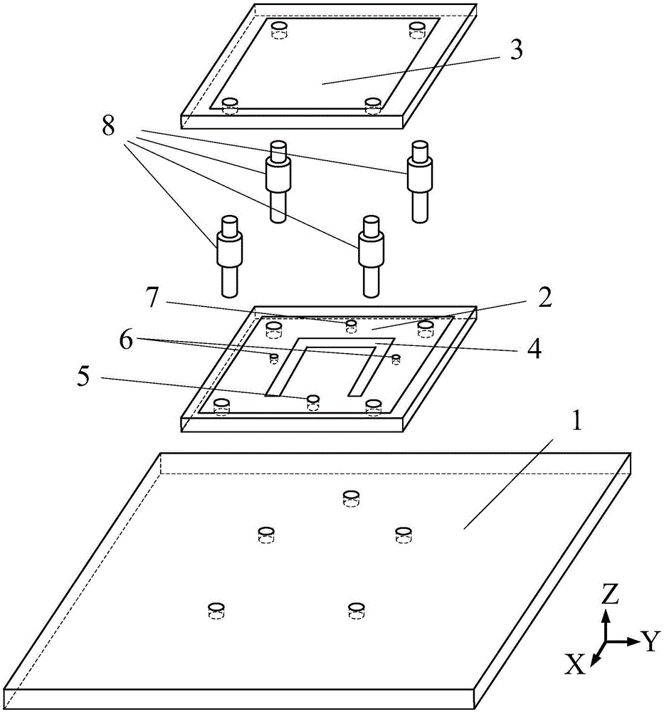
[0031] refer to figure 1 , The specific embodiment 1 of the filter patch antenna without an external filter circuit of the present invention is composed of a metal reflective floor 1 at the bottom, a feeding patch 2 in the middle, and a parasitic patch 3 at the top. The three are connected together and fixed through the through holes that are opened at the four corners respectively by plastic screws 8 . Metal reflective floors can be machined from brass, and feed and parasitic patches can...


PUM


Abstract

The invention discloses a filtering patch antenna without additional arrangement of filter circuit, and an adjustment method thereof. The antenna comprises a bottom metal reflection floor, an intermediate feed patch and a top parasitic patch. The two sides of the feed patch are each provided with a short circuit probe, the feed patch is provided with a U-shaped groove, a short circuit probe is arranged in front of an opening of the U-shaped groove, and a feed point is arranged behind a closing position of the U-shaped groove. The top parasitic patch is fixed right above the feed patch at an interval of a certain height. According to the invention, the filtering patch antenna itself has a filtering function and realizes a bandpass filtering characteristic without additional arrangement of the filter circuit. The passband edge is deep, the sideband suppression is obvious, the frequency selectivity is good, adjacent frequency interference can be inhibited, the bandpass filtering characteristic and an antenna radiation function are integrated together, the plat grain at a passband position is quite high, and the filtering patch antenna is applied to such mobile communication scenes as WCDMA, 4G-LTE, WLAN and the like.

Description

technical field [0001] The invention relates to an antenna in the field of wireless mobile communication, in particular to a filter patch antenna without an external filter circuit and an adjustment method thereof. Background technique [0002] In the field of wireless communication, in order to make full use of the spectrum resources allocated by the system, the spectrum interval between channels is generally set very small. On the other hand, the nonlinear effect of active devices in the communication system will generate a lot of clutter. When the clutter falls within the passband range of the receiver, it will cause adjacent frequency interference. This places stringent requirements on the frequency selectivity of RF front-ends in wireless communication systems. In practical applications, the communication system will perform power control, and a bandpass filter module will be added to the RF front end to filter out clutter outside the passband and suppress adjacent fre...

Claims


Application Information

Patent Timeline
Patent Type & Authority Applications(China)
IPC IPC(8): H01Q1/36H01Q1/48H01Q19/10H01Q1/12
Inventor 章秀银段文莫特潘咏梅
Owner SOUTH CHINA UNIV OF TECH
Why Eureka
Try Eureka