Demolding mechanism for multi-directional backoffs of plastic part of injection mold

A technology of injection mold and mold release mechanism, which is applied to the field of molding molds with multi-directional undercuts on plastic products, can solve the problems of large mold space, complex mold structure, large occupation, etc., and achieves simple and compact structure. Stable demoulding action, stable and reliable work

Active Publication Date: 2017-02-08
DALIAN LUANYI PRECISION ENG
View PDF7 Cites 5 Cited by
  • Summary
  • Abstract
  • Description
  • Claims
  • Application Information

AI Technical Summary

Problems solved by technology

[0002] The thermoplastic injection molding method is to melt the plastic material and inject it into the film cavity. The molten plastic enters the mold and is cooled to form a certain shape according to the mold cavity. The resulting shape is often the final product. Other processing is required; the undercut is a protruding or concave part set on the product to meet the needs of assembly and use. After molding, it cannot slide out along the mold parting direction. The existence of the undercut prevents the mold from fixing and moving. When the mold is separated, the product is directly separated from the mold, usually using a fixed mold or a movable mold slider mechanism, or using an inclined roof mechanism to realize the demoulding of the undercut. The device will cause the mold structure to be complex, occupying a large mold space, resulting in a larger mold shape and higher cost; in summary, in order to solve the shortcomings of the existing mold structure, it is necessary to design a structure that is simple, saves mold space, and saves Low-cost and easy-to-process multi-directional undercut ejection mechanism

Method used


Image

  • Demolding mechanism for multi-directional backoffs of plastic part of injection mold
  • Demolding mechanism for multi-directional backoffs of plastic part of injection mold
  • Demolding mechanism for multi-directional backoffs of plastic part of injection mold

Examples


Embodiment Construction

[0017] Specific embodiments of the invention will be described in detail below in conjunction with technical text and accompanying drawings.

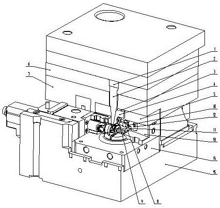
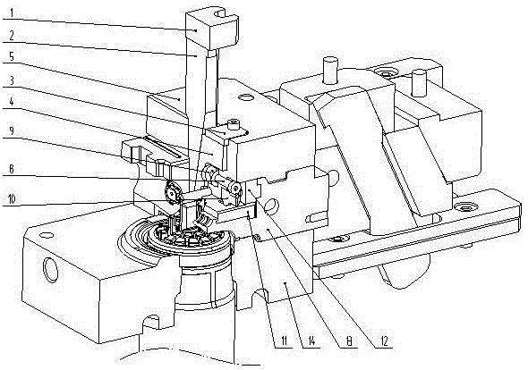
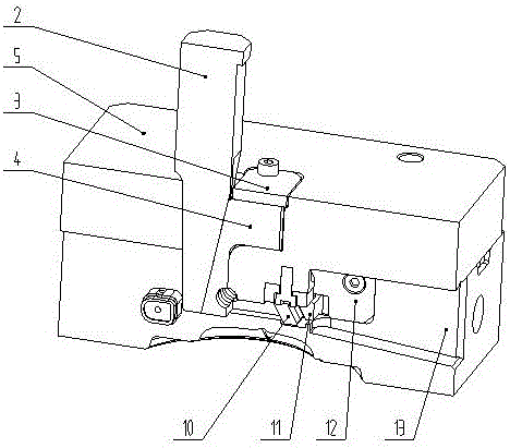
[0018] When assembling the mould, the fixed mold first draws the block 2 and installs it in the mold cavity processed by the fixed mold floating plate 6 and is limited by the hanging table. Firstly, the 2 sides of the drawing block are contacted and pressed tightly, and the bolt passes through the first pressure plate 1 to lock and fix it with the floating plate 6 of the fixed mold; the first spring 9 is installed in the cavity processed by the insert 5 of the fixed mold, and the fixed mold slides Block 4 is installed in the mold cavity processed by fixed mold insert 5 and is limited by a hanging table. The threads processed on the sliding block 4 are tightened and assembled. The second pressure plate 3 is installed in the cavity processed by the fixed mold insert 5 and is in contact with the surface of the fixed mold sliding block 5. ...


PUM


Abstract

The invention discloses a demolding mechanism for multi-directional backoffs of a plastic part of an injection mold, belonging to the field of thermoplastic plastic forming molds and being mainly applied to a forming mold of which a plastic product is provided with the multi-directional backoffs, the multi-directional backoffs of the plastic part of the injection mold can be smoothly demolded by virtue of the mold opening power of the mold and the elasticity of a spring instead of an additional power unit. The demolding mechanism has the beneficial effects that problems existing in the forming process of the multi-directional backoffs of the plastic part of the injection mold are solved by using the demolding mechanism for the multi-directional backoffs of the plastic part of the injection mold, and backoffs at the inner sides of plastic part products are demolded through the matched usage of a stationary mold first-pulling block 2, a stationary mold slide block 4, a shoulder bolt 8 and a first spring 9; backoffs at the outer sides of the plastic part products are demolded through the matched usage of a hook leg 10, a small slide block 11, a limiting insert 12 and a second spring 16; and the mold is smooth and reliable in structure and working, stable in demolding action, capable of enabling the product to meet the technical requirement and the use requirement and saving the mold space, reducing the cost and increasing the production efficiency as well as simple and compact in structure.

Description

technical field [0001] The invention belongs to the field of molding molds for thermoplastic plastics, and relates to a multi-directional undercut release mechanism for plastic parts of injection molds, which is mainly used in molding molds provided with multi-directional undercuts on plastic products. Background technique [0002] The thermoplastic injection molding method is to melt the plastic material and inject it into the film cavity. The molten plastic enters the mold and is cooled to form a certain shape according to the cavity. The resulting shape is often the final product. Other processing is required; the undercut is a protruding or concave part set on the product to meet the requirements of assembly and use. After molding, it cannot slide out along the mold parting direction. The existence of the undercut prevents the mold from fixing and moving. When the mold is separated, the product is directly separated from the mold, usually using a fixed mold or a movable ...

Claims


Application Information

Patent Timeline
Patent Type & Authority Applications(China)
IPC IPC(8): B29C45/33
CPCB29C45/33B29C45/332
Inventor 张嘉李世茂于春雨
Owner DALIAN LUANYI PRECISION ENG
Why Eureka
Try Eureka